Delta TP04 Series - Control Panel Instructions
- Instruction sheet (2 pages)
Advertisement
Introduction
Model Explanation
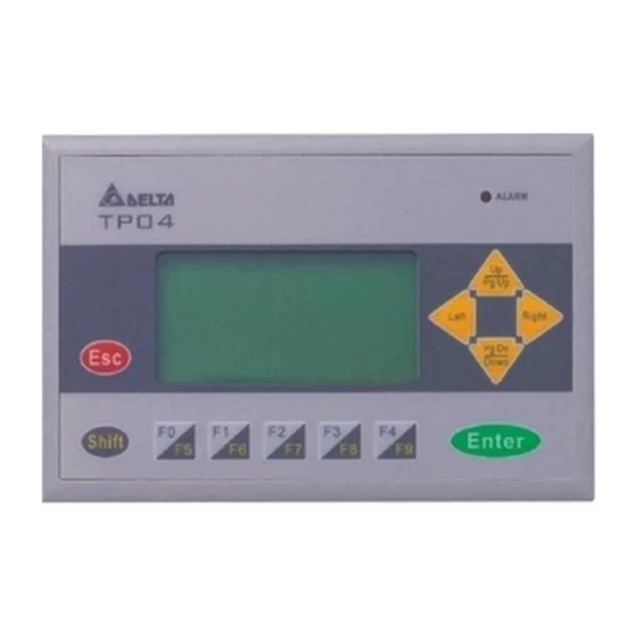
Thank you for choosing Delta TP Series. TP04G-AS2 has the features of high resolution 128×64 dots and is able to display 8×4 Chinese character. It provides multilingual display and two built-in communication ports, one is for RS-232 / RS-422 and the other is for RS-485. RS-232 and RS-485 can be used simultaneously. Besides, it also supports built-in RTC, communication / alarm LED indicators. The user can purchase program copy card (optional) to copy settings and programs quickly and save download time. Regarding the editing software, there are various objects and images for the user's requirements.
Nameplate Explanation

NOTE: The words of "MADE IN XXXXX" will be different due to the manufacturing location. Please refer to the actual product for exact description.
Model / Serial No. Explanation

Product Outline

Panel Function Explanation
| PANEL COMPONENT | EXPLANATION | |
| Alarm LED Indicator (RED) | Status 1: When power is on, LED will start to blink slowly Status 2: When there is an abnormal situation, LED will blink quickly along with an alarm sound. | |
| RS-232 LED Indicator (Yellow) | LED will blink when transmits program and communicates via RS-232. | |
| RS-485 / RS-422 LED Indicator (Green) | LED will blink when communicates via RS-485 / RS-422. | |
| Displaying Area | Liquid Crystal Module display area. It is used to display current program status. | |
| Escape / Exit Key | It is used to cancel an incorrect input, or to exit a programming step. | |
| Shift Key | It is used to select function keys F0 ~ F9 and other keys for special function. | |
| Arrow Keys | UP / Pg Up: It is used to increase the value or move up one page. Pg Dn / DOWN: It is used to decrease the value or move down one page. Left: This key is left direction key and it can be used to select the position of the value. Right: This key is right direction key and it can be used to select the position of the value. | |
| Enter Key | It is used to input a value or accept a programming command. | |
| Function Keys | F0 / F5: It is used to be constant 0 (F0) and 5 (Shift+F0) when it is in the system menu, the user can use it to define functions separately when they are in user page. F1 / F6: It is used to be constant 1 (F1) and 6 (Shift+F1) when it is in the system menu, the user can use it to define functions separately when they are in user page. F2 / F7: It is used to be constant 2 (F2) and 7 (Shift+F2) when it is in the system menu, the user can use it to define functions separately when they are in user page. F3 / F8: It is used to be constant 3 (F3) and 8 (Shift+F3) when it is in the system menu, the user can use it to define functions separately when they are in user page. F4 / F9: It is used to be constant 4 (F4) and 9 (Shift+F4) when it is in the system menu, the user can use it to define functions separately when they are in user page. | |
Back Panel

5 PIN terminal / Wire gauge: 12-24 AWG / Torque: 4.5 lb.-inch
Dimension

Installation
Please insert TP04 series to the opening hole of panel and tighten the screws. However, if a firm mounting TP04 series to the panel is needed, please use the mounting fixed support accessory which is packed together with TP04 series, then insert the fixed support in the back and tighten the screws.
 If the fixed support is not installed well, Delta will not guarantee the waterproof function. The screw torque should be 4-5(kg-cm). DO NOT exceed this specification when tightening the screws; otherwise TP04 series may be damaged. Please leave sufficient space (more than 50mm) around the unit for heat dissipation.
 Do not install and mount TP04 series in the following environment.
- A location subjected to Airborne dust, metallic particles, oil and smoke, corrosive or flammable gases and liquids.
- A location where temperature and humidity will exceed specifications.
- A location where vibration and shock will exceed specifications. ™
The flat surface should be a UL Type 4 "Indoor Use Only" enclosure or equivalent (IP65 / NEMA4).
Please refer to the figures below.
Please leave sufficient space (more than 50mm) around the unit for heat dissipation.


Function Specifications
| ITEM | TP04G-AS2 | |
| Screen Type | STN-LCD | |
| Display Color | Monochromatic | |
| Backlight | The back-light automatic turn off time is 1 ~ 99 minutes (0 = do not turn off) (The back-light life is about 50 thousand hours at 25°C) | |
| Resolution | 128x64 dots | |
| Display Range | (W) x (H) = 72 x 40 (unit: mm); 3.00" (diagonal preferred) | |
| Contrast Adjustment | 10 levels of adjustment | |
| Language / Font | ASCII: (Code page 850) Alphanumeric (including European characters) Taiwan: (Big 5 codes) Traditional Chinese Fonts China: (GB2324-80 codes) Simplified Chinese Fonts | |
| Display Text | 5×8 dots | 25 characters × 8 rows |
| 8×8 dots | 16 characters × 8 rows | |
| 8×12 dots | 16 characters × 5 rows | |
| 8×16 dots | 16 characters × 4 rows | |
| Font Size | ASCII: 5×8, 8×8, 8×12, 8×16 | |
| Alarm LED Indicator (RED) |
| |
| RS-232 LED Indicator (Yellow) | It will blink when transmitting program and communicating by using RS-232. | |
| RS-485 / RS-422 LED Indicator (Green) | It will blink when communicating by using RS-485 / RS-422. | |
| Program Memory | 256KB flash memory | |
| Serial Communication Port RS-232 (COM1) | Unsynchronized transmission method: RS-232 Data length: 7 or 8 bits, Stop bits: 1 or 2 bits Parity: None/Odd/Even, Transmission speed: 9,600bps ~ 115,200bps RS-232: 9 PIN D-SUB male | |
| Extension Communication Port RS-422 (COM1) RS-485 (COM2) | Unsynchronized transmission method: RS-485 / RS-422 Data length: 7 or 8 bits, Stop bits: 1 or 2 bits Parity: None/Odd/Even, Transmission speed: 9,600bps ~ 115,200bps RS-422: 9 PIN D-SUB male RS-485: 5 PIN removal terminal | |
| Extension Interface |
| |
| Battery Cover | DC 3V battery for HMI | |
| 5 PIN Removal Terminal | Include DC 24V input and RS-485 communication input | |
Electrical Specifications
| Specifications | TP04G-AS2 | |||
| Display | Monochromatic STN LCD | |||
| Effective Display Area | (W) x (H) = 72 x 40 (unit: mm); 3 inches | |||
| Display Resolution | 128×64 | 5×8 dots 8×8 dots 8×12 dots | 25 characters × 8 rows 16 characters × 8 rows 16 characters × 5 rows | |
| 8×16 dots | 16 characters × 4 rows | |||
| LCD Contrast Adjustment | Set by Software, adjust the contrast by the press button in the function table | |||
| LCD Backlight Type | LED Backlight: Automatic Turn-off Setting | |||
| Function / Numeric Keys | F0 ~ F9, ESC, SHIFT, ENTER and Arrow Keys | |||
| External Input Power | 24V (3.5W Max.) | |||
| Memory Capacity | 256K Byte | |||
| CPU | Hitachi HD64F3064F | |||
| RAM of System | 32K Byte | |||
| Communication Interface | COM1: RS-232 / RS422 COM2: RS-485 | |||
| Waterproof Class of Front Panel | IP65 / NEMA4 | |||
| Operating Temperature for Hardware | 0 ~ 50°C; 20 ~ 90﹪RH (non-condensing) | |||
| Storage Temperature for Hardware | -20 ~ 60°C | |||
| Vibration | 5Hz≦f 9Hz≦f≦150Hz = Continuous: 0.5g / Occasional: 1.0g | |||
| Shock | 15g peak, 11ms duration, half-sine, three shocks in each direction per axis, on 3 mutually perpendicular axes (total of 18 shocks) | |||
| Radiated Emission | CISPR11, Class A | |||
| Electrostatic Discharge Immunity | EN61000-4-2 | |||
| Radiated Immunity | EN61000-4-3 | |||
| Electrical Fast Transient | EN61000-4-4 | |||
| Weight / Dimensions | 0.24kg; 147×97×35.5mm (Width(W) × Height(H) × Deep(D)) | |||
| Cooling Method | Natural Air Cooling | |||
Program Copy Card
TP04 series provides Program Copy Card Function to copy user program, system function and passwords that is different from the copy program. It is used to copy the whole HMI environment settings and application programs to another HMI rapidly. Using Program Copy Card saves time and manpower. The operation is as follows. ™
Definition: Program Copy Card → PCC, TP Series → TP
| (TP→PCC) | (PCC→TP) | |
| Step 1 | Turn the switch on the PCC to TP→PCC | Turn the switch on the PCC to PCC→TP |
| Step 2 | Insert the PCC into the extension slot of TP | Insert the PCC into the extension slot of TP |
| Step 3 | Input the power to TP | Input the power to TP |
| Step 4 | It will display "remove PCC" on the screen and power on again. | It will display "remove PCC" on the screen and power on again. |
™ HMI Display Message
| (TP→PCC) | (PCC→TP) | |
| Step 1 | If the TP model type does not correspond with the model type of program of PCC, TP will display "TP series and PCC is different. Press Enter to Confirm TP seriesÆPCC. Press Esc to Exit". | If there is no program in PCC, TP will display "The PCC is Empty. PCC→TP series is illegal". |
| Step 2 | TP will display "TP→PCC series Please wait!" during transmission. | TP will display "PCC→TP series Please wait!" during transmission. |
| Step 3 | TP will display "Please Remove the PCC and Reboot" when transmission is completed. | TP will display "Please Remove the PCC and Reboot" when transmission is completed. |
Password Function
If the user forgot the password, the password can be cleared by using the following code: 8888. This universal code will clear the password and all TP04 series internal programs. The TP04 series will be reset to the factory settings by using this code also. Please pay close attention when using it.
™ The password can be the alphabet from A to Z or the number from 0 to 9. But it must use the function keys F0 ~ F9 to input the password characters. Please refer to the following table.
| Function Key | Use Method | Function Key | Use Method |
| F0 / F5 | Scrolls in a loop as follows 0→5→A→B→C→D→E→F→0 | F3 / F8 | Scrolls in a loop as follows 3→8→Q→R→S→T→U→V→3 |
| F1 / F6 | Scrolls in a loop as follows 1→6→G→H→I→J→K→1 | F4 / F9 | Scrolls in a loop as follows 4→9→W→X→Y→Z→4 |
| F2 / F7 | Scrolls in a loop as follows 2→7→L→M→N→O→P→2 |
Hardware Operation
When the user wants to startup TP04 series, a 24VDC power is needed. After applying 24VDC power to TP04 series, it will enter into the startup display and then enter the user-designed program. Pressing Esc key and holding on for 5 seconds can return to system menu. There are five selections in the system menu and are described below.
| SELECTIONS | EXPLANAION | |
| Download Program | Use the connection cable (DVPACAB530) to connect the TP04 serial communication port RS-232 to a PC. Then use the TPEdit software to download an application program to TP04. | |
| Upload Program | Use the connection cable (DVPACAB530) to connect the TP04 serial communication port RS-232 to a PC. Then use the TPEdit software to upload an application program from TP04. | |
| Copy Program | Transfer a program between two TP04 units. 1: transmit programs 2: receive programs When transmit programs and data between two TP04 units. Set one TP04 to "Receive Program" mode and the other TP04 to "Transmit Program" mode. Please use twisted pair wires to connect the two units via the RS-485 ports. | |
| TP04 Settings | There are 9 items that used to modify TP04 system settings:
| |
| PLC Connection | There are three methods to connect to PLC:
| |
| Execution | Execute the internal program that download from TPEdit or transmitted from other TP04 units. When program is in execution, the user can return to system menu by pressing Escape / Exit (Esc) key for 5 seconds. | |
Communication Connection
TP04G may connect to a PC by using connection able DVPACAB515
PC or TP02 / 04G


TP04G may connect to a DVP-PLC by using connection cable DVPACAB215 / DVPACAB230 / DVPACAB2A30
- DVPACAB215 / DVPACAB230

- DVPACAB2A30

![]()


The Pin definition of 9 PIN D-SUB
- RS-232
![]()
- RS-422
![]()
- DVPACAB630 (RS-422)


Switch between RS-422 / RS-485 (by using 8-PIN DIP switch)
| 8-PIN DIP Switch | RS-485 | RS-422 |
| SW1 ~ SW4 | On | Off |
| SW5 ~ SW8 | Off | On |
Battery Life and Precision of Calendar Timer
Battery Life
| Temperature (°C) | -20 | 0 | 20 | 60 |
| Life (Year) | 1.972 | 2.466 | 2.712 | 2.835 |
™ Precision of Calendar Timer
- At 0°C / 32°F, less than -117 seconds error per month.
- At 25°C / 77°F, less than 52 seconds error per month.
- At 55°C / 131°F, less than -132 seconds error per month.
http://www.delta.com.tw/industrialautomation/

Documents / ResourcesDownload manual
Here you can download full pdf version of manual, it may contain additional safety instructions, warranty information, FCC rules, etc.
Advertisement


Need help?
Do you have a question about the TP04 Series and is the answer not in the manual?
Questions and answers