Advertisement
Available languages
Available languages
Quick Links
上海菱本电子科技有限公司
High Color‧Wide Screen‧
-B08
DOP
User-Friendly HMI Products
No.18, Xinglong Rd., Taoyuan City
33068, Taiwan
B08S515 / B08E515 Instrunction Sheet
(1) Preface
Thank you for purchasing DELTA's DOP-B series. This instruction sheet will be helpful in the installation, wiring and inspection of
Delta HMI. Before using the product, please read this instruction sheet to ensure correct use. You should thoroughly understand all
safety precautions before proceeding with the installation, wiring and operation. Place this instruction sheet in a safe location for
future reference. Please observe the following precautions:
Install the product in a clean and dry location free from corrosive and inflammable gases or liquids.
Ensure that all wiring instructions and recommendations are followed.
Ensure that HMI is correctly connected to a ground. The grounding method must comply with the electrical standard of
the country (Please refer to NFPA 70: National Electrical Code, 2005 Ed.).
Do not disassemble HMI, modify or remove wiring when power is applied to HMI.
Do not touch the power supply during operation. Otherwise, it may cause electric shock.
If you have any questions during operation, please contact our local distributors or Delta sales representatives.
The content of this instruction sheet may be revised without prior notice. Please consult our distributors or download the most
updated version at
http://www.delta.com.tw/ia
(2) Safety Precautions
Carefully note and observe the following safety precautions when receiving, inspecting, installing, operating, maintaining and
troubleshooting. The following words, DANGER, WARNING and STOP are used to mark safety precautions when using the
Delta's HMI product. Failure to observe these precautions may void the warranty!
Installation
Comply with quick start for installation. Otherwise it may cause equipment damage.
Do not install the product in a location that is outside the stated specification for the HMI. Failure to
observe this caution may result in electric shock, fire, or explosion.
Do not install the product in a location where temperatures will exceed specification for the HMI.
Failure to observe this caution may result in abnormal operation or damage the product.
Please note that this equipment has obtained EMC registration for commercial use. In the event
that it has been mistakenly sold or purchased, please exchange it for equipment certified for home
use.
Do not use this product as an alarm device for disaster early warning that may result in personal
injury, equipment damage, or system emergency stop.
Wiring
Connect the ground terminals to a class-3 ground (Ground resistance should not exceed 100Ω).
Improper grounding may result in communication error, electric shock or fire.
Operation
The users should use Delta Screen Editor software to perform editing in Delta's HMI product. To
perform editing and confirming HMI programs without using Delta Screen Editor software in Delta's
HMI product may result in abnormal operation.
To prevent the personal injury and equipment damage, when designing HMI programs, please
ensure that a communication error occurred between Delta's HMI product and the connecting
controller or equipment will not result in system failure or malfunction.
Please be sure to backup the screen data and HMI programs in case they are lost, accidentally
deleted or worse.
Do not modify wiring during operation. Otherwise it may result in electric shock or personal injury.
Never use a hard or pointed object to hit or strike the screen as doing this may damage the screen
and let the screen has not respond at all, and then cause HMI to work abnormally.
Maintenance and Inspection
Do not touch any internal or exposed parts of the HMI as electrical shock may result.
Do not remove operation panel while power is on. Otherwise electrical shock may result.
Wait at least 10 minutes after power has been removed before touching any HMI terminals or
performing any wiring and/or inspection as an electrical charge may still remain in the HMI with
hazardous voltages even after power has been removed.
Turn the power off before changing backup battery and check system settings after finishing
change. (all data will be cleared after changing battery).
Be sure the ventilation holes are not obstructed during operation. Otherwise malfunction may result
due to bad ventilation or overheating troubles.
Wiring Method
Do not use a voltage that will exceed specification for the HMI. Failure to observe this caution may
result in electric shock or fire.
Remove the terminal block from the HMI before wiring.
Insert only one wire into one terminal on the terminal block.
If the wiring is in error, perform the wiring again with proper tools. Never use force to remove the
terminals or wires. Otherwise, it may result in malfunction or damage.
For the power line that forced to take out, ensure to check wiring again and restart.
Communication Wiring
Comply with communication wiring specification for wiring.
Wiring length should comply with the stated specification for the HMI.
Proper grounding to avoid bad communication quality.
To avoid noise and interference, the communication cable, all power cables, and motor power
cable should be placed in separate conduits.
上海菱本电子科技有限公司
服务热线:400 821 3454
(3) Pin Definition of Serial Communication
DOP-B08S515 / DOP-B08E515 COM1 Port (Supports Flow Control)
Contact
COM Port
PIN
RS-232
1
PIN1
2
RXD
3
TXD
4
5
GND
6
7
RTS
8
CTS
9
Note: Blank = No Connection.
DOP-B08S515 / DOP-B08E515 COM2 Port (Supports Flow Control)
MODE1
MODE2
COM Port
PIN
RS-232
RS-422
1
TXD+
2
RXD
PIN1
3
TXD
4
RXD+
5
GND
GND
6
TXD-
7
RTS
8
CTS
9
RXD-
Note1: Blank = No Connection.
Note2: When COM2 port is used for RS-232 flow control, i.e. RTS and CTS signals are used for flow control, COM3 port will become
incapable of being used.
Note3: When COM2 port is used for RS-422 flow control, please refer to the following COM3 Port signals table for pin assignments. The
signals, RTS+, CTS+, RTS- and CTS- shown in brackets are the signals used for flow control.
DOP-B08S515 / DOP-B08E515 COM3 Port
MODE1
MODE2
COM Port
PIN
RS-232
RS-422
1
TXD+(RTS+)
2
RXD
PIN1
3
TXD
4
RXD+(CTS+)
5
GND
GND
6
TXD-(RTS-)
7
8
9
RXD-(CTS-)
Note1: Blank = No Connection.
Note2: When COM2 port is used for RS-422 flow control, please refer to the COM3 Port signals table above for pin assignments. The signals,
RTS+, CTS+, RTS- and CTS- shown in brackets are the signals used for flow control.
DOP-B08E515 Ethernet Interface (LAN)
Contact
Ethernet Interface (LAN)
PIN
Ethernet
1
TX+
2
TX-
3
RX+
4
5
6
RX-
7
8
Note: Blank = No Connection.
服务热线:400 821 3454
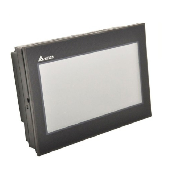
(4) Parts Names
DOP-B08S515 / DOP-B08E515 (Front View)
MODE3
RS-485
D+
GND
D-
: Power LED Indicator
A
Lights in green when HMI works normally.
: Operation LED Indicator (Blue)
The operation LED indicator blinks in blue when either the communication is carried out or the
C
data is accessing (please refer to the "Note1" below for explanation).
: Alarm LED Indicator (Red)
The alarm LED indicator blinks in red when one of the alarms is on.
MODE3
RS-485
D
Touch Screen / Display
D+
NOTE
GND
1. The definition of the operation LED indicator (Blue) can be determined by the users freely.
D-
DOP-B08S515 / DOP-B08E515 (Rear View)
A
Power Input Terminal
COM3
(It is provided with two LED indicators to
B
indicate that HMI is in Read or Write status
during the communication process.)
COM2
(It is provided with two LED indicators to
C
indicate that HMI is in Read or Write status
during the communication process.)
D
COM1
E
USB Slave
C
A
B
(Note1)
I
H
G
F
E
D
C
A
B
F
Ethernet Interface (LAN)
G
USB Host
H
Audio Output Interface
I
Memory Card Slot / Battery
-
-
Advertisement

Related Manuals for Delta DOP-B08


Summary of Contents for Delta DOP-B08
- Page 1 DOP-B08S515 / DOP-B08E515 COM2 Port (Supports Flow Control) Thank you for purchasing DELTA’s DOP-B series. This instruction sheet will be helpful in the installation, wiring and inspection of Delta HMI. Before using the product, please read this instruction sheet to ensure correct use. You should thoroughly understand all...
- Page 2 LED Back Light (less than 10,000 hours half-life at 25 Backlight Display 162 x 121.5mm Size Operation Delta Real Time OS System 32-bit RISC Micro-controller NOR Flash ROM Flash ROM 128 MB(OS System: 30MB / Backup: 16MB / User Application: 82MB) SDRAM 64Mbytes...
-
Page 3: Parça İsimleri
DOP-B08S515 / DOP-B08E515 COM2 Port (Flow Control destekler) DELTA’nın DOP-B serisi operatör panellerini seçtiğiniz için teşekkürler. Bu bilgi dökümanı Delta HMI kurulum, bağlantı, bakım ve kontrolünde kullanıcıya yardımcı olacaktır. Doğru kullanım için ürünü kullanmadan önce bu dökümanı mutlaka okuyunuz. Kurulum,... - Page 4 özelliklerde belirtilen güç değerinin 1.5 veya 2 katı güç tüketimini karşılayacak bir güç kaynağı ile kullanılması önerilir. Herhangi bir ihbar olmadan bu dökümanın içeriği değiştirilebilir. En son güncellenmiş halini firmamızdan talep edebilir yada aşağıdaki link adresinden indirebilirsiniz http://www.delta.com.tw/ia/. (6) Özellikler...
- Page 5 藍燈閃爍:通訊中/資料存取中(註) 在通電運作時,請勿接觸電源處,以免觸電。 動作指示燈 ( ) /警報指示燈 ( ) TXD- 紅燈閃爍:警報發生中 如果您在使用上仍有問題,請洽詢經銷商或者本公司客服中心。由於產品精益求精,當內容規格有所修正時,請洽詢代理 商或至台達網站(http://www.delta.com.tw/ia/)下載最新版本。 操作/顯示區域 RXD- 註 1:空白=不需連接 (2) 安全注意事項 註:藍色燈號顯示定義可由使用者自行設定 註 2:當 COM2 使用 RS-232 流量控制(RTS、CTS 腳位)時,COM3 則無法使用。 安裝、配線、操作、維護及檢查時,應隨時注意以下安全注意事項。 註 3:當 COM2 使用 RS-422 流量控制時,其流量控制腳位請參考 COM3 MODE2 括號內的腳位定義。 安裝注意...
- Page 6 LED Back Light(常溫 25 器 代理商或至台達網站 下載最新版本。 http://www.delta.com.tw/ia/ 顯示範圍 162 x 121.5mm 作業系統 Delta Real Time OS 中央處理器 32-bit RISC Micro-controller 記憶體 ROM Flash ROM 128 MB(OS System: 30MB / Backup: 16MB / User Application: 82MB) 內部記憶體 64Mbytes 斷電保持內部 16Mbytes 記憶體...
- Page 7 蓝灯闪烁:通讯中/数据存取中(注) 在通电运作时,请勿接触电源处,以免触电。 TXD- 动作指示灯 ( ) /警报指示灯 ( ) 如果您在使用上仍有问题,请咨询经销商或者本公司客服中心。由于产品精益求精,当内容规格有所修正时,请咨询代理 红灯闪烁:警报发生中 商或至台达网站(http://www.delta.com.tw/ia)下载最新版本。 RXD- 操作/显示区域 注 1:空白=不需连接 注 2:当 COM2 使用 RS-232 流量控制(RTS、CTS 引脚)时,COM3 则无法使用。 注:蓝色灯号显示定义可由使用者自行设定 (2) 安全注意事项 注 3:当 COM2 使用 RS-422 流量控制时,其流量控制引脚请参考 COM3 MODE2 括号内的引脚定义。 安装、配线、操作、维护及检查时,应随时注意以下安全注意事项。 DOP-B08S515 / DOP-B08E515 (背面) 安装注意...
- Page 8 背光灯 (Note 1) LED Back Light(常温 25 http://www.delta.com.tw/ia/ 器 显示范围 162 x 121.5mm 操作系统 Delta Real Time OS 中央处理器 32-bit RISC Micro-controller 内存 ROM Flash ROM 128 MB(OS System: 30MB / Backup: 16MB / User Application: 82MB) 内部存储器 64Mbytes 断电保持内部...
Need help?
Do you have a question about the DOP-B08 and is the answer not in the manual?
Questions and answers