KROHNE H250/M10 Installation And Operating Instructions Manual
Variable-area flowmeter
Hide thumbs
Also See for H250/M10:
- Supplementary instructions manual (16 pages) ,
- Supplementary instructions manual (16 pages)
Table of Contents
Advertisement
7022842100
KROHNE 11/2003
GM
www.krohne.com
Supplementary Installation and
Operating Instructions
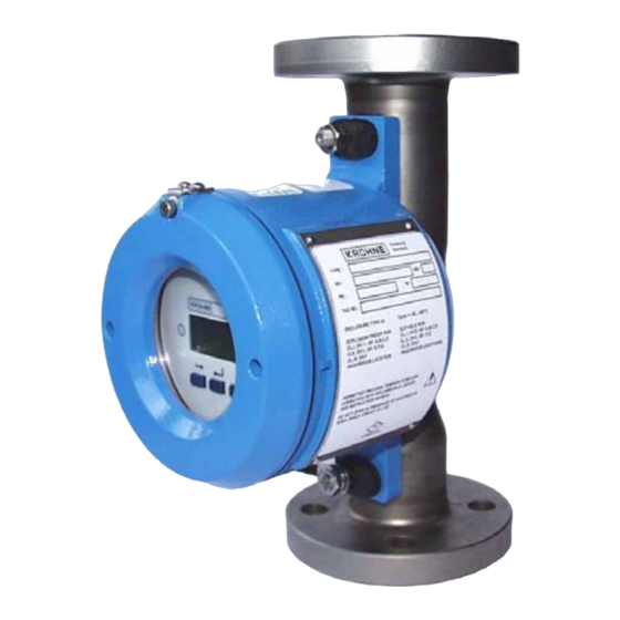
Variable-Area Flowmeter
H250/M10
Dust explosion protected
version Category II3D
II3D
Variable area flowmeters
Vortex flowmeters
Flow controllers
Electromagnetic flowmeters
Ultrasonic flowmeters
Mass flowmeters
Level measuring instruments
Communications technology
Engineering systems & solutions
Switches, counters, displays and recorders
Heat metering
Pressure and temperature
Advertisement
Table of Contents

Subscribe to Our Youtube Channel
Related Manuals for KROHNE H250/M10


Summary of Contents for KROHNE H250/M10
- Page 1 7022842100 KROHNE 11/2003 Supplementary Installation and Operating Instructions Variable-Area Flowmeter H250/M10 Dust explosion protected version Category II3D II3D Variable area flowmeters Vortex flowmeters Flow controllers Electromagnetic flowmeters Ultrasonic flowmeters Mass flowmeters Level measuring instruments Communications technology Engineering systems & solutions...
-
Page 2: Table Of Contents
Contents General safety information....................3 Description code ....................... 4 Main safety-relevant characteristics ................. 4 Process products..........................4 Category / Zone allocation....................... 4 Type of protection and marking ....................... 4 Special lock............................5 Cable entries / sealing plugs ......................5 Power supply ........................... 5 I/O functions............................. -
Page 3: General Safety Information
General safety information These additional Instructions apply to the dust explosion protected versions of H250/M10 with the category II3D. They are supplementary to the Installation and Operating Instructions for the non-dust -explosion protected versions Ident. No.: 702280##00. The information given in these Instructions contains only the data relevant to Category II3D explosion protection. -
Page 4: Description Code
Description code The safety-relevant Description code is made up of the following elements: *) H 2 5 0 / / M 1 0 Series measuring unit Unit H54 H250 Unit H250 Material / versions stainless steel stainless steel with PTFE liner (H250: PTFE / ceramic) Hastelloy (H250 only) Titan (H250 only) aseptic version (Food) (H250 only) -
Page 5: Special Lock
Special lock The sealing covers of the electronics compartment are secured by a special lock. The locking screw requires use of an Allen key (3 mm size). Cable entries / sealing plugs The H../../M10 variable-area flowmeter with Cat. II3D is provided alternatively with one or two cable entries. -
Page 6: Marking
Dependent to the max. operating temperature of the cable, the process temperatures are: Max. permissible process Ambient temperature permanent temperature in °C Wiring Wiring Wiring 70°C / 158°F 80°C / 176°F 90°C / 194°F °C °F °C °F °C °F °C °F -40 ... -
Page 7: Mounting And Installation
Mounting and installation Mounting and installation is to be carried out acc. to EN 50281-1-2:1998 by specialist personnel trained in explosion protection. The information given in the standard Installation and Operating Instructions, the Supplementary Installation and Operating Instructions and also in the EC Type Examination Certificate (see Attachment A.1) must be observed without fail. -
Page 8: Electrical Grounding
5.1.5 Electrical grounding • The signal converter must be incorporated in the equipotential bonding system of the hazardous location. The cable is to be connected to the outer press-fitted U-clamp terminal of the converter housing. • Connect the shields by the shortest possible route to the press-fitted U-clamp terminal (PE) in the terminal compartment. -
Page 9: Initial Startup
Initial startup Check the following points before initial startup: • Suitability of the materials used for the measuring tube and gaskets for adequate resistance to corrosion through the process product. • Compare the data on the nameplate on the signal converter with the existing operating data. •... -
Page 10: Replacement Of Signal Converter / Display
8.2.2 Replacement of signal converter / display Disconnect the device from supply before opening the Flameproof Enclosure. Be sure to follow the procedure described in Section 8.2.1. Note : Only same-type displays and complete converter housings may be replaced. Individual device inserts may not be replaced! Compare nameplates when replacing the signal converter. -
Page 11: Attachment A.1 Declaration Of Conformity Rl 94/9/Eg (Atex 100A)
Attachment A.1 Declaration of Conformity RL 94/9/EG (ATEX 100a) Supplementary Installation and Operating Instructions M10 EEx d... - Page 12 Supplementary Installation and Operating Instructions M10 EEx d...
Need help?
Do you have a question about the H250/M10 and is the answer not in the manual?
Questions and answers