KROHNE H250 M10 Supplementary Instructions Manual
Hide thumbs
Also See for H250 M10:
- Supplementary instructions manual (16 pages) ,
- Installation and operating instructions manual (12 pages)
Table of Contents
Advertisement
Quick Links
Advertisement
Table of Contents

Subscribe to Our Youtube Channel
Related Manuals for KROHNE H250 M10


Summary of Contents for KROHNE H250 M10
- Page 1 H250 M10 H250 M10 H250 M10 H250 M10 Supplementary instructions Supplementary instructions Supplementary instructions Supplementary instructions Ex supplementary instructions Equipment category II 3 D © KROHNE 03/2011 - 4001348101- MA H250/M10-Ex-II3G-AD R01 en...
-
Page 2: Table Of Contents
CONTENTS H250 M10 1 Safety instructions 1.1 General notes ........................3 1.2 EC conformity ........................3 1.3 Safety instructions......................3 2 Device description 2.1 Device description ......................4 2.2 Description code....................... 4 2.3 Marking..........................5 2.4 Flammable products ......................6 2.5 Equipment category ...................... -
Page 3: Safety Instructions
SAFETY INSTRUCTIONS H250 M10 1.1 General notes These additional instructions apply to explosion-protected versions of the H250/M10 variable area flowmeter with the designation II 3 D. They complement the Installation and Operating Instructions for the non-explosion protected versions. The information given in these Instructions contains only the data relevant to Category 3 explosion protection. -
Page 4: Device Description
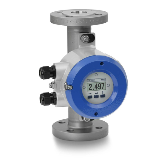
DEVICE DESCRIPTION H250 M10 2.1 Device description Variable area flowmeters measure and display the volume flow of flammable and non- flammable gases and liquids. The display unit contains a 4...20 mA signal output with optional HART® communication, two programmable electronic switch outputs and a reset input. -
Page 5: Marking
Additional markings on the device: • SN - serial number • SO - sales order / item • PA - KROHNE order • Vxxx - product configurator code • AC - article code 03/2011 - 4001348101- MA H250/M10-Ex-II3G-AD R01 en... -
Page 6: Flammable Products
DEVICE DESCRIPTION H250 M10 2.4 Flammable products Atmospheric conditions An explosive atmosphere is a mixture of air and flammable gases, vapours, mists or dusts under atmospheric conditions. The following values define it: = -20...+60°C / -4...+140°F and P = 0.8...1.1 bar. -
Page 7: Ambient Temperature / Temperature Classes
DEVICE DESCRIPTION H250 M10 2.7 Ambient temperature / temperature classes Because of the influence of the temperature of the product, no fixed temperature class is assigned to variable area flowmeters. In fact, the temperature class of a device is a function of the temperature of both the product and the environment. -
Page 8: Electrical Data
DEVICE DESCRIPTION H250 M10 For use in areas with flammable dust it should be noted that the indicated maximum surface temperature of T65°C at an ambient temperature of 60°C / 140°F and a product temperature of 60°C / 140°F is valid without a dust coating. For higher product temperatures the maximum surface temperature is determined by the product. -
Page 9: Installation
INSTALLATION H250 M10 3.1 Installation Installation and setup must be carried out according to the applicable installation installation standards (e.g. EN 60079-14) by qualified personnel trained in explosion protection. The information given in the Installation and Operation Instructions and the Supplementary Installation and Operation Instructions must always be observed. -
Page 10: Electrical Connections
ELECTRICAL CONNECTIONS H250 M10 4.1 General notes The signal circuits are electrically connected in the buit-in terminal compartment of the signal converter. Unused conduit entries should be closed using approved blind plugs and seals. Ensure that the seals are tight. -
Page 11: Earthing And Equipotential Bonding
ELECTRICAL CONNECTIONS H250 M10 4.4 Earthing and equipotential bonding The signal converter shall be connected to the equipotential bonding system of the hazardous area via the external grounding connection on the signal converter housing. The measuring unit and the signal converter are electrically connected via an equipotential bonding conductor. -
Page 12: Operation
OPERATION H250 M10 5.1 Start-up Start-up is only permitted when the variable area flowmeter: • is correctly installed in the system and connected. • has been checked for the proper state with regard to its installation and connection requirements. The user of the system must have it checked before start-up in compliance with the national regulations for checks before startup. -
Page 13: Service
SERVICE H250 M10 6.1 Maintenance Maintenance work of a safety-relevant nature within the meaning of explosion protection may only be carried out by the manufacturer, his authorised representative or under the supervision of authorised inspectors. For systems in hazardous areas, regular tests are required in order to maintain the proper condition. -
Page 14: Dismantling
SERVICE H250 M10 6.2 Dismantling Exchanging the built-in equipment Due to the modular design of the variable area flowmeter, it is possible to replace a complete signal converter and display with an identical spare part in accordance with safety guidelines. - Page 15 SERVICE H250 M10 03/2011 - 4001348101- MA H250/M10-Ex-II3G-AD R01 en www.krohne.com...
- Page 16 Measuring systems for the oil and gas industry • Measuring systems for sea-going tankers Head Office KROHNE Messtechnik GmbH Ludwig-Krohne-Str. 5 D-47058 Duisburg (Germany) Tel.:+49 (0)203 301 0 Fax:+49 (0)203 301 10389 info@krohne.de The current list of all KROHNE contacts and addresses can be found at: www.krohne.com...
Need help?
Do you have a question about the H250 M10 and is the answer not in the manual?
Questions and answers