Table of Contents
Advertisement
Quick Links
H250 M9
H250 M9
H250 M9
H250 M9
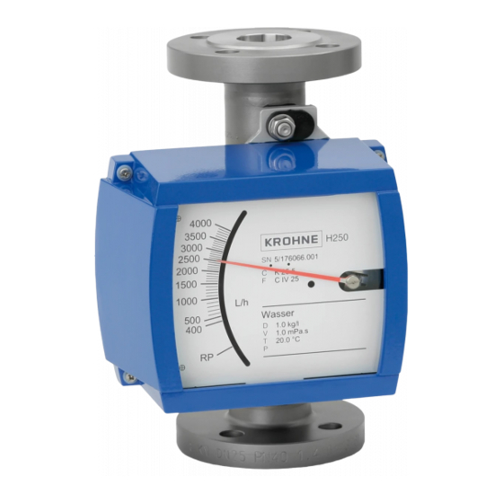
Variable area flowmeter
Equipment category II 3 G and II 3 D with electrical components
in protection type non-sparking 'nA' and
in protection type equipment - dust ignition protection 't'
© KROHNE 04/2015 - 4000646002 MA H250/M9-Ex-II3GD-AD-R06-en
Supplementary instructions
Supplementary instructions
Supplementary instructions
Supplementary instructions
Advertisement
Table of Contents

Subscribe to Our Youtube Channel
Related Manuals for KROHNE H250 M9


Summary of Contents for KROHNE H250 M9
- Page 1 Supplementary instructions Supplementary instructions Variable area flowmeter Equipment category II 3 G and II 3 D with electrical components in protection type non-sparking 'nA' and in protection type equipment - dust ignition protection 't' © KROHNE 04/2015 - 4000646002 MA H250/M9-Ex-II3GD-AD-R06-en...
-
Page 2: Table Of Contents
CONTENTS H250 M9 1 Safety instructions 1.1 General notes ........................3 1.2 EC conformity ........................3 1.3 Security information ......................3 2 Device description 2.1 Device description ......................4 2.2 Description code....................... 4 2.3 Marking..........................5 2.4 Flammable products ......................6 2.5 Equipment category ...................... -
Page 3: Safety Instructions
SAFETY INSTRUCTIONS H250 M9 1.1 General notes These additional Instructions apply to the explosion-protected versions of the variable area flowmeters with electrical components and the marking II 3 G and II 3 D. They complete the installation and operation instructions for the non-explosion protected versions. -
Page 4: Device Description
DEVICE DESCRIPTION H250 M9 2.1 Device description Variable area flowmeters are used to measure and display volume flows of flammable and non- flammable gases and liquids. Depending on the device version, electrical limit switches and a 4- 20 mA signal output or a Profibus PA interface can be built into the indicator part. -
Page 5: Marking
9 KROHNE website Additional markings on the device: • SN - serial number • SO - sales order / item • KO - KROHNE order • Vxxx - product configurator code • AC - article code Additional plate The association of the housing cover to the device is confirmed by an additional plate with the serial number on the interior of the indicator part. -
Page 6: Flammable Products
DEVICE DESCRIPTION H250 M9 2.4 Flammable products Atmospheric conditions: Atmospheric conditions: Atmospheric conditions: Atmospheric conditions: An explosive atmosphere is a mixture of air and flammable gases, vapours, mists or dusts under atmospheric conditions. It is defined by the following values T = -20...+60°C /... -
Page 7: Types Of Protection
DEVICE DESCRIPTION H250 M9 2.6 Types of protection 2.6.1 Type of protection for gas hazard areas The variable area flowmeter is designed with protection type "non-sparking" 'nA' in accordance with EN 60079-15. Protection against explosion is ensured in that no sparking contacts or hot surfaces lead to ignition under normal operating conditions. -
Page 8: Ambient Temperature / Temperature Classes
DEVICE DESCRIPTION H250 M9 2.7 Ambient temperature / temperature classes Due to the influence of the product temperature, variable area flowmeters with built-in electrical equipment (electric variants) are not assigned to any fixed temperature class. The temperature class of these devices is rather a function of the product temperature and ambient temperature that is present and the specific device version. - Page 9 DEVICE DESCRIPTION H250 M9 Using a heat resistant connecting cable Temperature table in °C Heating jacket ≤ 40 ≤ 60 none with HT-version DN15, DN25 DN15 DN50 DN25 DN80, DN100 DN50, DN80 Temperature table in °F Heating jacket ≤ 104 ≤...
- Page 10 DEVICE DESCRIPTION H250 M9 Maximum permitted product temperature in Maximum permitted product temperature in °C C C C Maximum permitted product temperature in Maximum permitted product temperature in Maximum permitted product temperature T Heating jacket T2, T1 ≤ 40 ≤ 60 ≤...
-
Page 11: Surface Temperature Equipment Category Ii 3 D
DEVICE DESCRIPTION H250 M9 2.8 Surface temperature equipment category II 3 D For use in areas with flammable dust it should be noted that the indicated maximum surface temperature of T65°C at an ambient temperature of 60°C / 140°F and a product temperature of 65°C / 149°F is valid without a dust coating. -
Page 12: Installation
INSTALLATION H250 M9 3.1 Installation Installation and setup must be carried out according to the applicable installation installation standards (e.g. EN 60079-14) by qualified personnel trained in explosion protection. The information given in the Installation and Operation Instructions and the Supplementary Installation and Operation Instructions must always be observed. -
Page 13: Electrical Connections
ELECTRICAL CONNECTIONS H250 M9 4.1 General notes Electrical connection of the signal circuits is carried out in the integrated terminal compartment of the indicator part. Separate conduit entries are provided for the signal output and limit switches. Unused conduit entries should be closed using approved blind plugs and seals. Ensure that the seals are tight. -
Page 14: Power Supply
ELECTRICAL CONNECTIONS H250 M9 4.2 Power supply The variable area flowmeter does not require any separate power supply. The necessary power for the built-in electrical equipment is supplied via the signal circuits. 4.3 Inputs/outputs The signal circuits of the variable area flowmeter may only be connected to downstream devices or circuits that satisfy the requirements of protective extra-low voltage (PELV). -
Page 15: Operation
OPERATION H250 M9 5.1 Start-up Start-up is only permitted when the variable area flowmeter: • is correctly installed in the system and connected. • has been checked for the proper state with regard to its installation and connection requirements. The user of the system must have it checked before start-up in compliance with the national regulations for checks before startup. -
Page 16: Service
SERVICE H250 M9 6.1 Maintenance Maintenance work of a safety-relevant nature within the meaning of explosion protection may only be carried out by the manufacturer, his authorised representative or under the supervision of authorised inspectors. For systems in hazardous areas, regular tests are required in order to maintain the proper condition. -
Page 17: Notes
NOTES H250 M9 04/2015 - 4000646002 MA H250/M9-Ex-II3GD-AD-R06-en www.krohne.com... - Page 18 NOTES H250 M9 www.krohne.com 04/2015 - 4000646002 MA H250/M9-Ex-II3GD-AD-R06-en...
- Page 19 NOTES H250 M9 04/2015 - 4000646002 MA H250/M9-Ex-II3GD-AD-R06-en www.krohne.com...
- Page 20 Measuring systems for the marine industry Head Office KROHNE Messtechnik GmbH Ludwig-Krohne-Str. 5 47058 Duisburg (Germany) Tel.:+49 203 301 0 Fax:+49 203 301 103 89 info@krohne.com The current list of all KROHNE contacts and addresses can be found at: www.krohne.com...
Need help?
Do you have a question about the H250 M9 and is the answer not in the manual?
Questions and answers