KROHNE H250 M10 Supplementary Instructions Manual
Variable area flowmeter
Hide thumbs
Also See for H250 M10:
- Supplementary instructions manual (16 pages) ,
- Installation and operating instructions manual (12 pages)
Table of Contents
Advertisement
H250 M10
H250 M10
H250 M10
H250 M10
Variable area flowmeter
Equipment category II 2G
Equipment category II 2G
Equipment category II 2G
Equipment category II 2G
© KROHNE 06/2012 - 4001058901- MA H250/M10-Ex-II2G-AD R02 en
Supplementary instructions
Supplementary instructions
Supplementary instructions
Supplementary instructions
Advertisement
Table of Contents

Related Manuals for KROHNE H250 M10


Summary of Contents for KROHNE H250 M10
- Page 1 H250 M10 H250 M10 Supplementary instructions Supplementary instructions Supplementary instructions Supplementary instructions Variable area flowmeter Equipment category II 2G Equipment category II 2G Equipment category II 2G Equipment category II 2G © KROHNE 06/2012 - 4001058901- MA H250/M10-Ex-II2G-AD R02 en...
-
Page 2: Table Of Contents
CONTENTS H250 M10 1 Safety instructions 1.1 General notes ........................3 1.2 EC conformity ........................3 1.3 Safety instructions......................3 2 Device description 2.1 Device description ......................4 2.2 Description code....................... 4 2.3 Marking..........................5 2.4 Flammable products ......................6 2.5 Equipment category ...................... -
Page 3: Safety Instructions
SAFETY INSTRUCTIONS H250 M10 1.1 General notes These additional instructions apply to explosion-protected versions of variable area flowmeters with electrical built-ins and the marking II 2 G. They complement the standard documentation for the non-explosion protected versions. The information given in these Instructions contains only the data relevant to Category 2 explosion protection. -
Page 4: Device Description
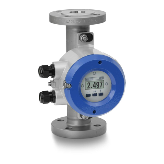
DEVICE DESCRIPTION H250 M10 2.1 Device description Variable area flowmeters measure and display the volume flow of flammable and non- flammable gases and liquids. The display unit contains a 4...20 mA signal output with optional ® HART communication, two programmable electronic switch outputs and a reset input. -
Page 5: Marking
DEVICE DESCRIPTION H250 M10 2.3 Marking Type designation of the complete unit is shown on the indicator with the nameplates reproduced below (see also description code). 1 Device type 2 Manufacturer 3 ATEX & DGRL certification agency code. 4 Year of manufacture 5 Production order No. -
Page 6: Flammable Products
DEVICE DESCRIPTION H250 M10 2.4 Flammable products Atmospheric conditions: Atmospheric conditions: Atmospheric conditions: Atmospheric conditions: An explosive atmosphere is a mixture of air and flammable gases, vapours, mists or dusts under atmospheric conditions. The following values define it = -20...+60°C / -4...+140°F and P = 0.8...1.1 bar. -
Page 7: Protection Types
DEVICE DESCRIPTION H250 M10 2.6 Protection types The variable area flowmeter is designed with protection type flameproof enclosure "d", acc. to EN 60079-1. The marking is: II 2G Ex d IIC T6 II 2G Ex d IIC T6 II 2G Ex d IIC T6... -
Page 8: Electrical Data
DEVICE DESCRIPTION H250 M10 Maximum permissible product and ambient temperatures per temperature class Temperature Ambient Product temperature at permanent service temperature class temperature of connecting cable 70°C / 158°F 80°C / 176°F 90°C / 194°F [°C] [°F] [°C] [°F] [°C] [°F]... -
Page 9: Installation
INSTALLATION H250 M10 3.1 Installation Installation and setup must be carried out according to the applicable installation standards (e.g. EN 60079-14) by qualified personnel trained in explosion protection. The information given in the manuals and the supplementary instructions must be observed at all times. -
Page 10: Electrical Connections
ELECTRICAL CONNECTIONS H250 M10 4.1 General notes Rated values for insulation • The insulation of the H.../../M10 - Ex variable area flowmeters is rated in compliance with IEC 60 664-1. The following rating parameters are taken into account: • Overvoltage category for signal and instrument loops: II •... -
Page 11: Inputs / Outputs
ELECTRICAL CONNECTIONS H250 M10 4.3 Inputs / outputs The signal circuits of the variable area flowmeter may only be connected to downstream devices or circuits that satisfy the requirements of protective extra-low voltage (PELV). Connecting power and I/O functions • Before connecting or disconnecting the electrical connection cables of the device, make sure that all cables leading to the converter are isolated from the ground of the hazardous area. -
Page 12: Earthing And Equipotential Bonding
ELECTRICAL CONNECTIONS H250 M10 4.4 Earthing and equipotential bonding The signal converter shall be connected to the equipotential bonding system of the hazardous area via the external grounding connection on the signal converter housing. The measuring unit and the signal converter are electrically connected via an equipotential bonding conductor. -
Page 13: Operation
OPERATION H250 M10 5.1 Start-up Start-up is only permitted when the variable area flowmeter: • is correctly installed in the system and connected. • has been checked for the proper state with regard to its installation and connection requirements. • and the electronics compartment have been properly closed (pressure-resistant casing) and the applicable special lock has been fitted. -
Page 14: Service
SERVICE H250 M10 6.1 Maintenance Maintenance work of a safety-relevant nature within the meaning of explosion protection may only be carried out by the manufacturer, his authorised representative or under the supervision of authorised inspectors. To maintain proper condition, regular inspections are required for systems in hazardous areas. - Page 15 SERVICE H250 M10 CAUTION! Faulty prisms between the measuring tube and the display housing should be replaced. Exchanging the entire device Observe the information above. Also, ensure that all process connections and the pipeline are depressurized and free of product. Where environmentally critical products are concerned, carefully decontaminate the wetted parts of the flange system after dismantling.
- Page 16 • Measuring systems for the marine industry Head Office KROHNE Messtechnik GmbH Ludwig-Krohne-Str. 5 47058 Duisburg (Germany) Tel.:+49 (0)203 301 0 Fax:+49 (0)203 301 10389 info@krohne.de The current list of all KROHNE contacts and addresses can be found at: www.krohne.com...
Need help?
Do you have a question about the H250 M10 and is the answer not in the manual?
Questions and answers