Table of Contents
Advertisement
Advertisement
Table of Contents

Subscribe to Our Youtube Channel
Related Manuals for KROHNE H250 M9


Summary of Contents for KROHNE H250 M9
- Page 1 H250 M9 H250 M9 H250 M9 H250 M9 Supplementary instructions Supplementary instructions Supplementary instructions Supplementary instructions Variable area flowmeter Device category II2G with electrical internals © KROHNE 03/2013 - 4002553501 MA H250/M9-NEPSI Ex i AD R01 en...
-
Page 2: Table Of Contents
CONTENTS H250 M9 1 Safety instructions 1.1 General notes ........................3 1.2 NEPSI conformity ......................3 1.3 Security information ......................3 2 Device description 2.1 Device description ......................4 2.2 Description code....................... 4 2.3 Marking..........................5 2.4 Flammable products ......................6 2.5 Device category ........................ -
Page 3: Safety Instructions
SAFETY INSTRUCTIONS H250 M9 1.1 General notes These additional instructions apply to explosion-protected versions of variable area flowmeters with electrical built-ins and the marking Ex ia IIC T1 - T6 Gb. They complete the installation and operation instructions for the non-explosion protected versions. -
Page 4: Device Description
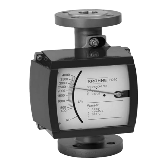
DEVICE DESCRIPTION H250 M9 2.1 Device description Variable area flowmeters measure and display the volume flow of flammable and non- flammable gases and liquids. Depending on the device version, electrical limit switch contacts and a 4...20 mA signal output or a Profibus PA interface can be installed in the display. -
Page 5: Marking
DEVICE DESCRIPTION H250 M9 2.3 Marking Type designation of the complete unit is shown on the indicator with the nameplates reproduced below (see also description code). 1 Device type 2 Manufacturer 3 Sizing data: temperature & pressure rating 4 PED data... -
Page 6: Flammable Products
DEVICE DESCRIPTION H250 M9 2.4 Flammable products Atmospheric conditions: Atmospheric conditions: Atmospheric conditions: Atmospheric conditions: An explosive atmosphere is a mixture of air and flammable gases, vapours, mists or dusts under atmospheric conditions. The following values define it = -20...+60°C / -4...+140°F and P = 0.8...1.1 bar. -
Page 7: Ambient Temperature / Temperature Classes
DEVICE DESCRIPTION H250 M9 2.7 Ambient temperature / temperature classes Due to the influence of the product temperature, variable area flowmeters with built-in electrical equipment (electric variants) are not assigned to any fixed temperature class. The temperature class of these devices is rather a function of the product temperature and ambient temperature that is present and the specific device version. - Page 8 DEVICE DESCRIPTION H250 M9 Using a heat resistant connecting cable Temperature table in °C Heating jacket ≤ 40 ≤ 60 none with HT-version DN15, DN25 DN15 DN50 DN25 DN80, DN100 DN50, DN80 Temperature table in °F Heating jacket ≤ 104 ≤...
- Page 9 DEVICE DESCRIPTION H250 M9 Maximum permitted product temperature in °C C C C Maximum permitted product temperature in Maximum permitted product temperature in Maximum permitted product temperature in Maximum permitted product temperature T [°C] Heating jacket T2, T1 ≤ 40 ≤...
- Page 10 DEVICE DESCRIPTION H250 M9 Maximum permitted product temperature in °F F F F Maximum permitted product temperature in Maximum permitted product temperature in Maximum permitted product temperature in Maximum permitted product temperature T [°F] Heating jacket T2, T1 ≤ 104 ≤...
-
Page 11: Electrical Data
DEVICE DESCRIPTION H250 M9 2.8 Electrical data Electrical equipment Nominal voltage Nominal current Limit switch K1 / K2 8 VDC 1...3 mA Signal output ESK II and ESK2A 24 VDC ± 25% ® 4...20 mA with HART communication ESK3-PA Profibus transmitter 9...24 VDC... -
Page 12: Installation
INSTALLATION H250 M9 3.1 Installation Installation and setup must be carried out according to the applicable installation standards by qualified personnel trained in explosion protection. Variable area flowmeters must be installed in such a way that • There is no danger from mechanical impact effects. -
Page 13: Electrical Connections
ELECTRICAL CONNECTIONS H250 M9 4.1 General notes The connecting cables should be selected according to the applicable installation standards and the maximum operating temperature. The outside diameter of the connecting cables must be matched to the sealing area of the conduit entry/entries. The connecting cables must be laid and fastened securely in such a way that they are adequately protected against damage. -
Page 14: Operation
OPERATION H250 M9 5.1 Start-up Start-up is only permitted when the variable-area flowmeter: • is correctly installed in the system and connected. • has been checked for the proper state with regard to its installation and connection requirements. The user of the system must be have it checked before start-up in compliance with the national regulations for checks before start-up. -
Page 15: Service
SERVICE H250 M9 6.1 Maintenance Maintenance work of a safety-relevant nature within the meaning of explosion protection may only be carried out by the manufacturer, his authorised representative or under the supervision of authorised inspectors. To maintain proper condition, regular inspections are required for systems in hazardous areas. -
Page 16: Attachment
ATTACHMENT H250 M9 www.krohne.com 03/2013 - 4002553501 MA H250/M9-NEPSI Ex i AD R01 en... - Page 17 ATTACHMENT H250 M9 03/2013 - 4002553501 MA H250/M9-NEPSI Ex i AD R01 en www.krohne.com...
- Page 18 ATTACHMENT H250 M9 www.krohne.com 03/2013 - 4002553501 MA H250/M9-NEPSI Ex i AD R01 en...
- Page 19 ATTACHMENT H250 M9 03/2013 - 4002553501 MA H250/M9-NEPSI Ex i AD R01 en www.krohne.com...
- Page 20 ATTACHMENT H250 M9 www.krohne.com 03/2013 - 4002553501 MA H250/M9-NEPSI Ex i AD R01 en...
-
Page 21: Notes
NOTES H250 M9 03/2013 - 4002553501 MA H250/M9-NEPSI Ex i AD R01 en www.krohne.com... - Page 22 NOTES H250 M9 www.krohne.com 03/2013 - 4002553501 MA H250/M9-NEPSI Ex i AD R01 en...
- Page 23 NOTES H250 M9 03/2013 - 4002553501 MA H250/M9-NEPSI Ex i AD R01 en www.krohne.com...
- Page 24 • Measuring systems for the marine industry Head Office KROHNE Messtechnik GmbH Ludwig-Krohne-Str. 5 47058 Duisburg (Germany) Tel.:+49 (0)203 301 0 Fax:+49 (0)203 301 10389 info@krohne.de The current list of all KROHNE contacts and addresses can be found at: www.krohne.com...
Need help?
Do you have a question about the H250 M9 and is the answer not in the manual?
Questions and answers