KROHNE DK37/M8 Supplementary Instructions Manual
Variable area flowmeter
Hide thumbs
Also See for DK37/M8:
- Supplementary instructions manual (16 pages) ,
- Supplementary instructions manual (20 pages)
Table of Contents
Advertisement
Quick Links
DK37/M8 - H250/M8
DK37/M8 - H250/M8
DK37/M8 - H250/M8
DK37/M8 - H250/M8
Variable area flowmeter
Equipment protection level Gb
in type of protection Intrinsic Safety "i"
© KROHNE 11/2017 - 4002616802 - AD DK37 NEPSI Ex ia R02 en
Supplementary Instructions
Supplementary Instructions
Supplementary Instructions
Supplementary Instructions
Advertisement
Table of Contents

Related Manuals for KROHNE DK37/M8


Summary of Contents for KROHNE DK37/M8
- Page 1 DK37/M8 - H250/M8 DK37/M8 - H250/M8 Supplementary Instructions Supplementary Instructions Supplementary Instructions Supplementary Instructions Variable area flowmeter Equipment protection level Gb in type of protection Intrinsic Safety "i" © KROHNE 11/2017 - 4002616802 - AD DK37 NEPSI Ex ia R02 en...
-
Page 2: Table Of Contents
CONTENTS DK37/M8 - H250/M8 1 Safety instructions 1.1 General notes ........................3 1.2 NEPSI conformity ......................3 1.3 Approval according to the IECEx scheme ................ 3 1.4 Safety instructions......................4 2 Device description 2.1 Device description ......................5 2.2 Description code....................... 6 2.3 Marking.......................... -
Page 3: Safety Instructions
1.2 NEPSI conformity Variable-area flowmeters, type DK37/M8 and H250/M8 series have been approved by NEPSI (National Supervision and Inspection Center for Explosion Protection and Safety of Intrumentation). This product is in accordance with the following standards: •... -
Page 4: Safety Instructions
SAFETY INSTRUCTIONS DK37/M8 - H250/M8 1.4 Safety instructions If these instructions are not followed, there is a risk of explosion. Assembly, installation, start-up and maintenance may only be performed by personnel trained in explosion protection! CAUTION! The operator or his agent is responsible for observing any additional standards, directives or laws if required due to operating conditions or place of installation. -
Page 5: Device Description
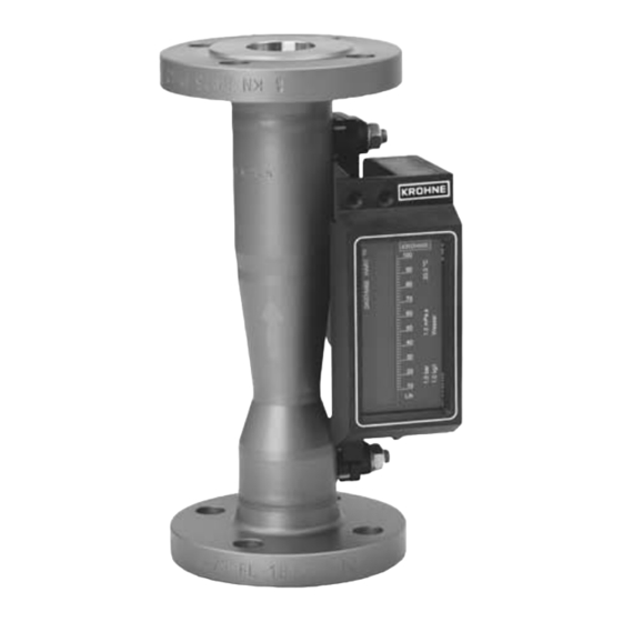
DEVICE DESCRIPTION DK37/M8 - H250/M8 2.1 Device description Variable area flowmeters measure and display the volume flow of flammable and non- flammable gases and liquids. The M8E. 1 indicator has a signal output 4...20 mA with a bargraph indicator. The M8M. 2 indicator has up to two separately adjustable electrical limit switches. -
Page 6: Description Code
DEVICE DESCRIPTION DK37/M8 - H250/M8 2.2 Description code Type series H250 Type series H250 Type series H250 Type series H250 The safety description code * consists of the following elements: 1 Type series measuring unit H250 2 Materials / versions... - Page 7 DEVICE DESCRIPTION DK37/M8 - H250/M8 Type series DK37 Type series DK37 Type series DK37 Type series DK37 The safety description code * consists of the following elements: 1 Type series of measuring unit DK 2 Type series of signal converter 37...
-
Page 8: Marking
DEVICE DESCRIPTION DK37/M8 - H250/M8 2.3 Marking Figure 2-1: Example of nameplate 1 Product designation 2 Manufacturer name and address 3 Sizing data: temperature & pressure rating 4 PED data 5 Marking according to NEPSI and permissible ambient temperature range... -
Page 9: Flammable Products
DEVICE DESCRIPTION DK37/M8 - H250/M8 2.4 Flammable products Atmospheric conditions: Atmospheric conditions: Atmospheric conditions: Atmospheric conditions: The ATEX directive does not stipulate values for atmospheric conditions. However, for determining the explosion characteristic parameters of temperature and pressure range, the following is assumed as a basis: = -20...+60°C / -4...+140°F and P... -
Page 10: Protection Types
DEVICE DESCRIPTION DK37/M8 - H250/M8 2.6 Protection types The variable area flowmeter is designed in type of protection intrinsic safety "i". The marking for equipment protection level Gb is: Ex ia IIC T3-T6 Gb Ex ia IIC T3-T6 Gb Ex ia IIC T3-T6 Gb... -
Page 11: Ambient Temperature / Temperature Classes / Product Temperature
For certain device versions, lower values apply due to differing boundary conditions (e.g. liner materials). Here the user should consult the technical data sheet. The maximum product temperature is outlined in the following tables. DK37/M8../../.. permissible product and ambient temperatures Temperature Ambient temperature... - Page 12 DEVICE DESCRIPTION DK37/M8 - H250/M8 Temperature Ambient temperature Maximum permissible product temperature / maximum value class up to Type DK37/M8E/.. Type DK37/M8M/..K. Type DK37/M8M/..K. at 64 mW at 169 mW [°C] [°F] [°C] [°F] [°C] [°F] [°C] [°F] +104 +135...
-
Page 13: Electrical Data
DEVICE DESCRIPTION DK37/M8 - H250/M8 The permitted ambient temperature range is indicated on the nameplate; depending on the device version it is = -40...+65°C / -40...+149°F or T = -25...+65°C / -13...+149°F. The minimum product temperature is -40°C / -40°F. -
Page 14: Installation
INSTALLATION DK37/M8 - H250/M8 3.1 Mounting Mounting and setup must be carried out according to the applicable installation standards (e.g. GB 3836.15) by qualified personnel trained in explosion protection. The information given in the standard documentation and the supplementary instructions must be observed at all times. -
Page 15: Electrical Connections
ELECTRICAL CONNECTIONS DK37/M8 - H250/M8 4.1 General notes The built-in equipment is connected electrically in the indication unit. The circuits are designed in type of protection Intrinsic Safety and are galvanically isolated from ground (test voltage ≥ 500 V The connecting cables should be selected according to the applicable installation standards and the maximum operating temperature. -
Page 16: Power Supply
ELECTRICAL CONNECTIONS DK37/M8 - H250/M8 Indicator M8E - M8EG 1 Connection signal output 4...20 mA 4.2 Power supply The variable area flowmeter does not require a separate power supply. The necessary power for the built-in electrical equipment is supplied via the signal circuits. -
Page 17: Grounding And Equipotential Bonding
ELECTRICAL CONNECTIONS DK37/M8 - H250/M8 4.4 Grounding and equipotential bonding If the device is not sufficiently electrostatically grounded via the process cables, an additional ground connection must be established using the ground terminal 1. The position of the ground terminal is illustrated below. This connection only ensures electrostatic grounding of the device and does not meet the requirements for equipotential bonding. -
Page 18: Operation
OPERATION DK37/M8 - H250/M8 5.1 Start-up Start-up is only permitted when the variable area flowmeter: • is correctly installed in the system and connected. • has been checked for the proper state with regard to its installation and connection requirements. -
Page 19: Service
SERVICE DK37/M8 - H250/M8 6.1 Maintenance Maintenance work of a safety-relevant nature within the meaning of explosion protection may only be carried out by the manufacturer, his authorised representative or under the supervision of authorised inspectors. For systems in hazardous areas, regular checks are required in order to maintain the proper condition. - Page 20 • Process Analysis • Services Head Office KROHNE Messtechnik GmbH Ludwig-Krohne-Str. 5 47058 Duisburg (Germany) Tel.: +49 203 301 0 Fax: +49 203 301 10389 info@krohne.com The current list of all KROHNE contacts and addresses can be found at: www.krohne.com...
Need help?
Do you have a question about the DK37/M8 and is the answer not in the manual?
Questions and answers