Advertisement
Quick Links
KNX Consumption Interface
ZRX-KCI4SO
FEATURES
•
4 channels for consumption counters (meters) with S0-pulse outputs
(UNE-EN 62053-31) *.
•
Registration of consumed electric power, cost and CO2 emissions that
can be split in up to 4 time intervals.
•
Compliant with UNE-EN 62053-31 Class B.
•
Total data saving on KNX bus power failure.
•
KNX BCU integrated.
•
Size 90 x 60 x 35 mm (2 DIN units).
•
DIN rail unit assembly (EN 50022), with snap fit clamp.
•
CE directives compliant (CE mark on the front side).
*Other counters (meters) with dry-voltage output or not complying S0 standard
may also work (previous test is recommended)
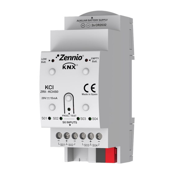
1. Battery holder
5. Programming LED
Programming button: short press to set programming mode. If this button is held while plugging the device into the KNX bus, it enters the safe mode.
Programming LED: programming mode indicator (red). When the device enters the safe mode, it blinks (red) every half second. During the start-up
(reset or after KNX bus failure) and if the device is not in safe mode, it emits a red flash.
LOW batt. LED: if this LED is blinking in red, replace the batteries as soon as possible.
EMPTY batt. LED: if this LED is blinking in red, the batteries are empty.
GENERAL SPECIFICATIONS
CONCEPT
Type of device
Voltage (typical)
Voltage range
KNX supply
Maximum
consumption
Connection type
External power supply
Operation temperature
Storage temperature
Operation humidity
Storage humidity
Complementary characteristics
Protection class
Operation type
Device action type
Electrical stress period
Degree of protection
Installation
Minimum clearances
Response on KNX bus failure
Response on KNX bus restart
Operation indicator
Weight
PCB CTI index
Housing material
¹ Maximum consumption in the worst case scenario (KNX Fan-In model)
© Zennio Avance y Tecnología S.L.
2. EMPTY batt. LED indicator
6. Input Indicator LED
Voltage
29VDC (typical)
24VDC¹
Edition 5
3. LOW batt. LED indicator
7. Input connectors
DESCRIPTION
Electric operation control device
29VDC SELV
21..31VDC
mA
12.5
15
Typical TP1 bus connector for 0.80mm Ø rigid cable
2 CR2032 battery (2 x 3V). It allows to keep counting pulses without the
KNX bus power supply
0°C .. +55°C
-20°C .. +55°C
5 .. 95% (No condens.)
5 .. 95% (No condens.)
Class B
III
Continuous operation
Type 1
Long
IP20, clean environment
Independent device to be mounted inside electrical panels with DIN rail (EN
50022)
Not required
Data saving according to parameterization
Data recovery according to parameterization
Programming LED indicates programming mode (red) or safe mode
(blinking red). LOW and EMPTY batt. LED indicate the battery level when
blinking in red (KNX supply necessary). LED input indicator blinks when a
pulse is received
89g (+ 6g bat.)
175V
PC FR V0 halogen free
Futher information
TECHNICAL DOCUMENTATION
1
3
4
5
6
7
Figure 1: KCI
4. Programming button
8. KNX connector
mW
363
360
www.zennio.com
KCI
2
8
Page 1/2
Advertisement

Related Manuals for Zennio ZRX-KCI4SO


Summary of Contents for Zennio ZRX-KCI4SO
- Page 1 Weight 89g (+ 6g bat.) PCB CTI index 175V Housing material PC FR V0 halogen free ¹ Maximum consumption in the worst case scenario (KNX Fan-In model) © Zennio Avance y Tecnología S.L. Edition 5 Futher information www.zennio.com Page 1/2...
- Page 2 • Keep the device away from water and do not cover it with clothes, paper or any other material while in use. • The WEEE logo means that this device contains electronic parts and it must be properly disposed of by following the instructi ons at http://zennio.com/weee-regulation. © Zennio Avance y Tecnología S.L. Edition 5 Futher information www.zennio.com...
Need help?
Do you have a question about the ZRX-KCI4SO and is the answer not in the manual?
Questions and answers