Table of Contents
Advertisement
Quick Links
UM2757
User manual
Getting started with X-NUCLEO-53L3A2 multi target ranging ToF sensor
expansion board based on VL53L3CX for STM32 Nucleo
Introduction
This document provides detailed hardware information on the X-NUCLEO-53L3A2 expansion board. This expansion board is
compatible with the STM32 Nucleo family and the Arduino™ electronic boards. It is designed around the VL53L3CX ranging
sensor and is based on the ST patented FlightSense technology.
To allow the user to validate the VL53L3CX in an environment as close as possible to its final application, the
X‑NUCLEO-53L3A2 expansion board is delivered with a holder in which three different height spacers of 0.25 mm, 0.5 mm, and
1 mm can be fitted with the cover glass above the spacer. The height spacers are used to simulate different air gap distances
between the VL53L3CX sensor and the cover glass.
The X-NUCLEO-53L3A2 expansion board is delivered with two VL53L3CX breakout boards.
UM2757 - Rev 2 - April 2021
www.st.com
For further information contact your local STMicroelectronics sales office.
Advertisement
Table of Contents

Related Manuals for ST X-NUCLEO-53L3A2


Summary of Contents for ST X-NUCLEO-53L3A2
- Page 1 VL53L3CX for STM32 Nucleo Introduction This document provides detailed hardware information on the X-NUCLEO-53L3A2 expansion board. This expansion board is compatible with the STM32 Nucleo family and the Arduino™ electronic boards. It is designed around the VL53L3CX ranging sensor and is based on the ST patented FlightSense technology.
- Page 2 UM2757 Figure 1. X-NUCLEO-53L3A2 expansion board, spacers, cover glass, and breakout boards UM2757 - Rev 2 page 2/17...
-
Page 3: Overview
It is compatible with the STM32 Nucleo development board family, and with the Arduino UNO R3 connector layout. Several ST expansion boards can be stacked through the Arduino connectors, which allows, for example, the development of VL53L3CX applications with Bluetooth or Wi-Fi interfaces. -
Page 4: Document References
UM2757 Document references Document references Table 2. Document references Description DocID VL53L3CX datasheet DS13204 X-NUCLEO-53L3A2 data brief DB4226 P-NUCLEO-53L3A2 data brief DB4194 X-CUBE-53L3A2 data brief DB4193 UM2757 - Rev 2 page 4/17... -
Page 5: Nucleo-53L3A2 Expansion Board
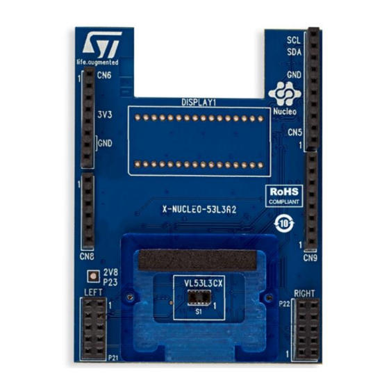
UM2757 X-NUCLEO-53L3A2 expansion board X-NUCLEO-53L3A2 expansion board This section describes the X-NUCLEO-53L3A2 expansion board features and provides useful information for understanding the electrical characteristics. Figure 2. X-NUCLEO-53L3A2 expansion board schematic diagram UM2757 - Rev 2 page 5/17... -
Page 6: Description
Table 3. Left Arduino connector Table 4. Right Arduino connector. The X-NUCLEO-53L3A2 must be plugged onto the STM32 Nucleo development board through the Arduino UNO R3 connectors. Figure 3. X-NUCLEO-53L3A2 expansion board connector layout AVDD... - Page 7 UM2757 Description Table 3. Left Arduino connector VL53L3CX X-NUCLEO-53L3A2 expansion CN number Pin number Pin name MCU pin board board function IOREF Not used RESET Power 3.3 V supply CN6 power Not used Not used Interrupt signal from VL53L3CX on...
- Page 8 UM2757 Description Table 4. Right Arduino connector VL53L3CX X-NUCLEO-53L3A2 expansion CN number Pin number Pin name MCU pin board board function I2C1_SCL I2C1_SDA AVDD Not used INT_L CN5 digital Not used GPIO1_L INT_L By default not used, interrupt signal from optional VL53L3CX left...
-
Page 9: Electrical Schematic
UM2757 Electrical schematic Electrical schematic Figure 4. X-NUCLEO-53L3A2 expansion board schematic VL53L3 VL53L1 VL53L3CX application VL53L3CX * Can be NC or grounded UM2757 - Rev 2 page 9/17... -
Page 10: List Of Materials
UM2757 List of materials List of materials Table 5. List of materials Components Value Reference Supplier Comments VL53L3CX application C1, C3 100 nF Supply voltage decoupling 4.7 µF X5R - 6.3 V 47 k Interrupt output pull up 47 k Reset input pull up R66, R67 4.7 k... -
Page 11: Solder Drop Configurations
UM2757 Solder drop configurations Solder drop configurations Solder drops allow the following configurations of the X-NUCLEO-53L3A2 expansion board: • If the developer wants to make an application with several expansion boards stacked and there is: – conflict with the microcontroller port allocation, the GPIO1 can be output on the CN8/A4 (U17 fitted) of the Arduino connector. -
Page 12: Integrated Device Pinning
UM2757 Integrated device pinning Integrated device pinning Figure 6. Integrated device pinning STMPE1600 A1 INT VCC SDA SCL LD39050PUR TPS3838 GPIO_0 GPIO_1 GPIO_15 RESET GPIO_2 GPIO_14 GPIO_3 GPIO_13 ST2329A VL VCC GPIO_4 GPIO_12 GPIO_5 GPIO_11 VCC1 VCC2 TOP VIEWS GPIO_6 GPIO_9 GPIO_7 GPIO_8... -
Page 13: Vl53L3Cx Breakout Board
UM2757 VL53L3CX breakout board VL53L3CX breakout board The VL53L3CX breakout boards are supplied at 2.8 V by the regulator present on the X-NUCLEO-53L3A2 expansion board. Figure 7. VL53L3CX breakout board schematic The VL53L3CX breakout boards can be directly plugged onto the X-NUCLEO-53L3A2 expansion board through the two 10-pin connectors or connected to the board through flying leads. -
Page 14: Safety Considerations
UM2757 Safety considerations Safety considerations Electrostatic precaution The user should exercise electrostatic precautions, including using ground straps when using the X- NUCLEO-53L3A2 expansion board. Failure to prevent electrostatic discharge could damage the device. Figure 9. Electrostatic logo Laser safety considerations The VL53L3CX contains a laser emitter and corresponding drive circuitry. -
Page 15: Revision History
UM2757 Revision history Table 6. Document revision history Date Version Changes 10-Sep-2020 Initial release 23-Apr-2021 Updated Figure 2. X-NUCLEO-53L3A2 expansion board schematic diagram UM2757 - Rev 2 page 15/17... -
Page 16: Table Of Contents
X-NUCLEO-53L3A2 expansion board........ - Page 17 ST’s terms and conditions of sale in place at the time of order acknowledgement. Purchasers are solely responsible for the choice, selection, and use of ST products and ST assumes no liability for application assistance or the design of Purchasers’...
Need help?
Do you have a question about the X-NUCLEO-53L3A2 and is the answer not in the manual?
Questions and answers