Advertisement
Quick Links
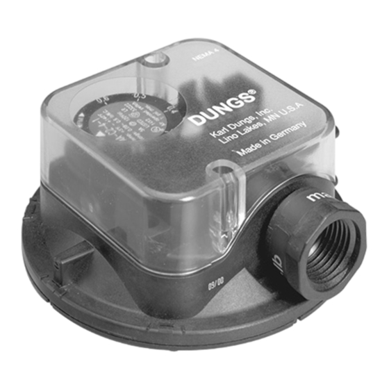
AA...C2 Differential Air Pressure Switch
Installation Instructions
AA...C2 SPDT Differential pressure switch in pressure and vacuum ranges. The differential pressure acts via the diaphragm
against the force of the setting spring on the microswitch. The pressure switch operates without any auxiliary power.
Gases
Air and non-aggressive gases. Not suitable for natural
gas, propane, butane and other combustable gases.
Switch
SPDT
Switch action
Pressure, vacuum or differential pressure switch.
Contact Rating
5 A resistive, 2.5A inductive @120 Vac
1A @ 12V-48Vdc
Electrical Connection
Screw terminals via 1/2" NPT conduit connection
Enclosure
NEMA Type 4
• Read these instructions carefully.
• Failure to follow them and/or improper installation may
cause explosion, property damage and injuries.
• Installation must be done with the supervision of a
licensed burner technician.
• Check the ratings in the specifications to make sure that
it is suitable for your application.
• Never perform work if gas pressure or power is applied,
or in the presence of an open flame.
• Ensure that the switch is not subjected to vibration during
operation.
Phone: (763) 582-1700 Fax: (763) 582-1799 E-mail: info@karldungsusa.com
1 ... 4
SPECIFICATIONS
MODELS DESIGNATIONS AND RANGES
Type
Version
AA-C2-4-...
AA-C2-4-1
AA-C2-4-2
AA-C2-4-3
3890 Pheasant Ridge Dr. NE, Suite 150, Blaine, MN 55449 U.S.A.
Maximum Operating Pressure
20 In W.C. (50 mbar)
Ambient / Medium Temperature
+5°F to +140°F (-15°C to +60 °C)
Materials in contact with Gas
Housing:
Switch:
Diaphragm:
Switching contact:
Approvals
UL Listed: File #.MH16628
CSA: Certificate #: 201527
FM Approved: Report J.1.0D6A1.AF
Commonwealth of Massachusetts Approved Product
Approval code G3-0106-191
ATTENTION
• Once installed, perform a complete checkout including
leak testing.
• Label all wires prior to disconnection when servicing.
Wiring errors can cause improper and dangerous
operation
• Verify proper operation after servicing.
• The system must be installed, used, and maintaned to
meet all applicable national and local code requirements
such as but not limited toNFPA 86, NFPA 160,
ANSI Z83.4/ CSA 3.7, ANSI Z83.18/CSA 4.9,
ANSI Z21.13, CSD-1, UL 795, CAN1-3.1, CGA 3.2,
CSA 3.8, CSA B149.1, or CSA B149.3.
Order No.
Setting range
in. W.C
217-333A
0.08 - 0.60
217-334A
0.16 - 1.20
217-336A
0.40 - 4.00
Karl Dungs, Inc
Polycarbonate
Polycarbonate
NBR-based rubber
Silver (Ag)
Advertisement

Subscribe to Our Youtube Channel
Related Manuals for Dungs AA C2 Series


Summary of Contents for Dungs AA C2 Series
- Page 1 AA-C2-4-1 217-333A 0.08 - 0.60 AA-C2-4-2 217-334A 0.16 - 1.20 AA-C2-4-3 217-336A 0.40 - 4.00 Karl Dungs, Inc 3890 Pheasant Ridge Dr. NE, Suite 150, Blaine, MN 55449 U.S.A. Phone: (763) 582-1700 Fax: (763) 582-1799 E-mail: info@karldungsusa.com 1 … 4...
- Page 2 SWITCH HYSTERSIS AND PRESSURE CONNECTIONS 4 x o 0.1 (4 x o 2.5) 0.5 (12) deep Definition of switching hysteresis ∆p The pressure difference between the upper and lower switching pressures. APPLICATION AND CONNECTION EXAMPLES Connection p1 Connection p2 Connection p1 Connection p2 Connection p2 Connection p1 must remain open Blower monitoring System vacuum monitor Filter monitoring To monitor a filter, the AA...C2 can be For blower monitoring, connect con- AA...C2 is connected to the air duct connected as shown above.
- Page 3 WIRING • Remove the clear cover from the switch. AA...C2 switching function • Use 14 or 16 AWG wire rated for at least 75°C. As pressure rises: • Route the wires through the conduit connector. 1 NC opens, 2 NO closes • Connect the wiring to the appropriate screw terminals. As pressure falls: • Replace the clear cover. 1 NC closes, 2 NO opens CAUTION: All wiring must comply with local electri- cal codes, ordinances and regulations. CAUTION: Do not exceed the switch ratings given in the specifications and on the switch. OPERATION • Use an accurate pressure gauge connected upstream from Adjusting the Set Point the switch to measure the actual pressure. • Mount switch in the intended operation position. • Replace the clear cover. • Remove the clear cover from the switch. • Adjust the set point to the desired set point pressure by Automatic Reset turning the dial until the desired pressure is opposite the...
- Page 4 ACCESSORIES Accessory Order No. Klima-Set (Duct mounting kit) 217-897 Replacement cover 228-732 Mounting bracket (plastic) 230-273 120 VAC light mounting kit (orange) 231-772 24 Vdc light mounting kit (orange) 231-774 120 VAC light (green) 248-240 (for switches with light mouting kit 231-772 already installed) Replacement PG 11 conduit adapter 220-566 DIN connector (female plug) 210-318 Male plug for DIN connector 219-659 4 … 4...
Need help?
Do you have a question about the AA C2 Series and is the answer not in the manual?
Questions and answers