Advertisement
Quick Links
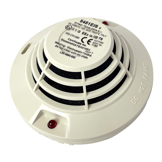
INSTALLATION AND MAINTENANCE INSTRUCTIONS FOR MODEL 5451EIS INTRINSICALLY
SAFE RATE-OF-RISE THERMAL DETECTOR WITH FIXED TEMPERATURE ALARM
Before installing the sensor, please thoroughly read System Sensor's Guide to Conventional Fire Systems. This manual includes detailed
information on sensor spacing, placement, zoning, and special applications. Copies of this manual are available at no charge from System Sensor.
GENERAL DESCRIPTION
Model 5451EIS is an intrinsically safe rate-of-rise thermal detector with fixed temperature alarm utilizing a state-of-the-art dual thermistor
sensing circuit. These detectors are designed to provide open area protection and are for use in hazardous areas where potentially explosive
atmospheres are likely to arise. The classification of equipment required must be confirmed with your responsible authority. The detectors are
designed to be used with compatible panels only and must be used in conjunction with a compatible zener barrier or galvanic isolator.
Two LEDs on each detector light to provide a local 360° visible alarm indication. Remote LED annunciator capability is available as an optional
accessory wired to the standard base terminals. These detectors also have a latching alarm feature. The alarm can be reset only by a momentary
power interruption. These detectors may be tested by activating an internal reed switch with a magnet.
SPECIFICATIONS
Size:
Cover Height:
60 mm
Cover Diameter:
102 mm
Weight:
277 g
Operating Temperature Range:
-10°C to 40°C
Operating Humidity Range:
10% to 93% Relative Humidity, Non-condensing
Intrinsic Safety Rating:
EEx ia IIB T5
Latching Alarm:
Reset by momentary power interruption.
This detector has been independently tested and certified to EN54 part 5 Class A1R and BASEEFA approved for intrinsic safety.
COVERAGE
As a general guide, the detector should provide adequate protection of an area 70-90m², where the ceiling is smooth and there is no significant air
movement. Where installation conditions or response requirements vary, different spacing may be necessary. It is essential to consult local
codes of practice for the installation of fire alarm systems before installing thermal detectors.
BASE SELECTION AND WIRING GUIDE
Refer to the installation instructions supplied with the plug-in detector bases for wiring details. System Sensor detector bases B401 and B401DG
are available for this detector.
All bases are provided with screw terminals for power and remote indicator connections. The electrical ratings for each detector-base
combination are also included in the base installation instructions.
NOTE:
All wiring must conform to applicable local and national codes and regulations.
NOTE:
Verify that all detector bases are installed, that the detector monitoring circuits have been tested and that the wiring is correct. (Refer to
detector base instructions for testing procedure)
Remove power from detector monitoring circuits before installing detectors.
INSTALLATION
1.
Place the detector into the detector base.
2.
Rotate the detector clockwise with gentle pressure until the detector drops into place.
3.
Continue rotating the detector clockwise to lock it in place.
4.
After all detectors have been installed, apply power to the detector monitoring circuits.
5.
Test the detector as described under TESTING.
6.
Reset the detector at the system control panel.
7.
Notify the proper authorities that the system is in operation.
Tamper-Resistance
The detector bases include a feature that, when activated, prevents removal of the detector without the use of a tool. See the installation
instructions for the detector base for details of how to use this feature.
Dust covers are fitted to the detectors to help protect units during shipment and when first installed. They are not intended to
provide complete protection against contamination; therefore detectors should be removed before beginning construction, major
re-decoration or other dust producing activity. Dust covers must be removed before the system can be made operational.
D400-50-00
WARNING
CAUTION
LED
0832
0832-CPD-0283
TEST MODULE
SOCKET
LED
TESTING
Detectors must be tested after installation and following periodic maintenance.
However, before testing, notify the proper authorities that the detector system is
undergoing maintenance and the system will be temporarily out of service. Disable the
zone or system undergoing maintenance to prevent unwanted alarms.
IMPORTANT: If testing is carried out using non-intrinsically safe methods, it must be conducted outside the hazardous area.
Test the detector as follows:
Test Magnet (Model M02-24 - optional)
1.
Test the detector by positioning the test magnet against the detector body approximately 2cm from LED1 in the direction of the metering
socket (see Figure 1).
2.
Both LEDs should latch on within 30 seconds, indicating an alarm and activating the panel.
Calibrated Sensitivity Test (MOD400R)
IMPORTANT: MOD400R is not intrinsically safe - the test must be conducted outside the hazardous area
1.
Use the MOD400R Test Module with a digital or analogue voltmeter to check detector sensitivity as described in the test module manual.
Direct Heat Method (Hair dryer of 1000-1500 watts)
IMPORTANT: This method is not intrinsically safe - the test must be conducted outside the hazardous area
1.
From the side of the detector, direct the heat toward the sensor. Hold the heat source about 15cm away to prevent damage to the cover
during testing. Note: If a detector goes into alarm, it will only reset if the detector has cooled and if its power is momentarily interrupted.
Check the control panel being used to determine whether the RESET switch (or some other auxiliary device or control) momentarily cuts off
power to the detector loop.
After completion of all tests notify the proper authorities that the system is operational.
Detectors that fail these tests should be cleaned as described under MAINTENANCE and re-tested. If the detectors still fail these tests they
should be returned for repair.
MAINTENANCE
Before cleaning, notify the proper authorities that the system is undergoing maintenance and will be temporarily out of service. Disable the
system to prevent unwanted alarms.
1.
Remove the detector to be cleaned from the system.
2.
Use a vacuum cleaner to remove dust from the sensing chamber.
3.
Reinstall the detector.
4.
When all sensors have been cleaned, restore power to the system and test the sensor(s) as described in the TESTING section of this
manual.
The Detector has a plastic enclosure that may present an electrostatic risk and must not be installed in a position where it may be
subject to a high dust-laden air flow. Clean only with a damp cloth and do not rub.
Heat sensors are designed to protect property, not life. They do not provide early warning of fire and cannot detect smoke, gas, combustion
particles or flame. The 5451E alarms when temperature at the heat sensor reaches 60°C. Given the rapid growth of certain types of fire, heat
sensors cannot be expected to provide adequate warning of fires resulting from smoking in bed, inadequate fire protection practices, violent
explosions, escaping gas, improper storage of flammable liquids like cleaning solvents, other safety hazards or arson.
Heat sensors do not always detect fires because the fire may be a slow smouldering, low-heat type (producing smoke) or because
they may not be near where the fire occurs or because the heat of the fire may bypass them. Heat sensors will not detect smoke, gas,
flames or combustion particles.
Heat sensors are components in professionally installed fire alarm systems. They will not function if they have been improperly wired into
the fire alarm system or if power to them is cut for any reason.
Heat sensors cannot last forever. They should be tested and maintained following the instructions in this manual. To be safe, they should be
replaced after they have been installed for 15 years.
1
Pittway Tecnologica S.r.l, Via Caboto 19/3, 34147 Trieste, Italy
TEST
PAINTED
MAGNET
SURFACE
TEST
MAGNET
Figure 1. Test Magnet Positioning.
CAUTION
WARNING
LIMITATIONS OF HEAT SENSORS
Figure 2. Sensor and Base
© System Sensor 2006
I56-2631-002
Advertisement

Subscribe to Our Youtube Channel
Related Manuals for System Sensor 5451EIS


Summary of Contents for System Sensor 5451EIS
- Page 1 Before installing the sensor, please thoroughly read System Sensor’s Guide to Conventional Fire Systems. This manual includes detailed Figure 1. Test Magnet Positioning. information on sensor spacing, placement, zoning, and special applications. Copies of this manual are available at no charge from System Sensor. GENERAL DESCRIPTION...
- Page 2 0832 Typical 5451EIS System Diagram 0832-CPD-0283 SAFE AREA HAZARDOUS AREA Safe area apparatus, which is (NOTE 5) (NOTE 2) unspecified except that it must not SHUNT ZENER DECLARATION OF CONFORMITY be supplied from or contain under DIODE SAFETY BARRIER OR...
Need help?
Do you have a question about the 5451EIS and is the answer not in the manual?
Questions and answers