Welch Allyn Connex 6000 Series Service Manual
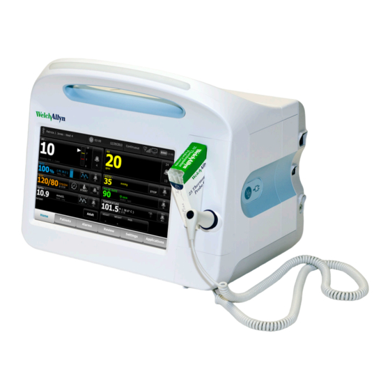
Vital signs monitor
Hide thumbs
Also See for Connex 6000 Series:
- Service manual (298 pages) ,
- Service manual (131 pages) ,
- Directions for use manual (143 pages)
Table of Contents
Advertisement
Advertisement
Table of Contents


Need help?
Do you have a question about the Connex 6000 Series and is the answer not in the manual?
Questions and answers