Table of Contents
Advertisement
Quick Links
Advertisement
Table of Contents

Related Manuals for REMKO Smart-Com SC-1


Summary of Contents for REMKO Smart-Com SC-1
- Page 1 Operating and installation instructions REMKO SC-1 Smart-Com For the room air conditioner BL, ML, MVV, MXD, MXT, MXW, RVD, RVT, RWT and RXT Manual for experienced specialists 0335-2023-02 Edition 1, en_GB Read the instructions prior to performing any task!
- Page 2 Read these operating instructions carefully before commis- sioning / using this device! These instructions are an integral part of the system and must always be kept near or on the device. Subject to modifications; No liability accepted for errors or mis- prints! Translation of the original...
-
Page 3: Table Of Contents
2.2 Unit dimensions..........................7 2.3 Scope of delivery..........................7 Operation............................... 8 3.1 General operation........................... 8 3.2 External access via REMKO Smart Web..................12 3.3 Activating KNX programming mode ..................... 14 Electrical wiring and interfaces......................15 4.1 Connections and interfaces......................15 4.2 Electrical wiring for the air conditioning units................ -
Page 4: Safety And Usage Instructions
REMKO SC-1 Smart-Com Safety and usage instructions CAUTION! This combination of symbol and signal word 1.1 General safety notes warns of a potentially hazardous situation, which if not avoided may cause injury or mate- Carefully read the operating manual before com- rial and environmental damage. -
Page 5: Safety Notes For The Operator
"certificate of warranty" to The setup, connection and operation of the REMKO GmbH & Co. KG at the time when the units and its components must be undertaken units are purchased and commissioned. -
Page 6: Transportation And Packaging
REMKO SC-1 Smart-Com 1.11 Transportation and packaging The units are shipped in sturdy transport pack- aging. Immediately check the units on delivery and make a note of any damage or missing parts on the delivery note. Inform the forwarding agent and contractual partner. -
Page 7: Technical Data And Scope Of Delivery
Technical data and scope of delivery 2.1 Unit data Series Smart Control Touch Operating mode Remote control Power supply +12 V DC Enclosure class Max. power consumption Max. cable length Recommended cable type (connecting line) sheathed, min. 0.5 Environment Ambient temperature °C 0-70 Air humidity... -
Page 8: Operation
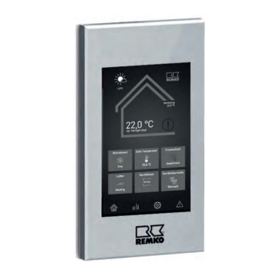
The tiles can be used to The REMKO Smart Control Touch regulation is an make further settings. The selection of tiles to be operating module with touch display. No buttons displayed in the overview display can be set indi- are required to adjust and change parameters. - Page 9 The information displayed varies depending on The settings are preset individually for each the authorisation level (user/expert level). If indoor unit. These settings are the basis for several indoor units have been combined as a selecting the operating mode in the "Overview" group, they are still displayed individually in this menu.
- Page 10 Enable expert level: You can access the expert level via the REMKO logo in the top right corner of the screen. You will be asked to enter the expert password, which is "0321".
- Page 11 Fig. 12: WPA2 Personal Authentication the expert level must be called up by pressing the REMKO logo in the upper right corner of the dis- When WPA2 Personal authentication is selected, play. A password must then be input using the the two items "SSID"...
-
Page 12: External Access Via Remko Smart Web
If there is a stable network connection between the router and the Smart Control Touch, it is possible with the REMKO Smart Web interface to mirror the display of the Smart Control Touch to a terminal device via the Internet. - Page 13 Indoor unit serial number The serial number of the indoor unit can be read from the name plate of the indoor unit, which is For the most stable connection possible, we located behind the front panel for wall units and recommend connecting via LAN cable.
-
Page 14: Activating Knx Programming Mode
User In this window, additional users can be added to operate the controller and access to the REMKO service (limited to 1 hour) can be granted. Editing a unit Here, it is possible to edit the data that was input when adding the device. -
Page 15: Electrical Wiring And Interfaces
Electrical wiring and interfaces 4.1 Connections and interfaces Unit BUS connection (A2/B2) The connecting line between the Smart Control Touch and the units to be controlled is connected to the contacts A2 (X) and B2 (Y). The conductor E must be connected to the GND terminal of the power supply. -
Page 16: Electrical Wiring For The Air Conditioning Units
REMKO SC-1 Smart-Com 4.2 Electrical wiring for the air conditioning units Connection variants The Smart Control Touch is connected to the X, Y and E contacts of the indoor units in single-split and multi- split systems. With VRF systems of the MVV series, the required connections are located on the outdoor unit. - Page 17 Fig. 22: Multi-split system connection A: SC-1 Smart-Com 1: Communication line B: Indoor unit 2: Flush-mounted power supply unit or power C: Indoor unit 2, 3, 4, etc. supply unit with Euro plug...
- Page 18 REMKO SC-1 Smart-Com Fig. 23: VRF system connection A: SC-1 Smart-Com 2: Flush-mounted power supply unit or power B: Outdoor unit type MVV ...DC supply unit with Euro plug 1: Communication line...
-
Page 19: Electrical Wiring To The Knx Network
4.3 Electrical wiring to the KNX network Connection variants The SC-1 Smart-Com has an interface to connect a KNX over IP network. If the SC-1 Smart-Com is to be connected to a KNX Twisted-Pair network, an IPInterface (accessories) or an IP router is required. Fig. - Page 20 REMKO SC-1 Smart-Com Fig. 25: Connection to a KNX TP network A: KNX controller (KNX TP) E: SC-1 Smart-Com B: Power supply 24-30V DC 1: KNX-TP bus line C: Router / network switch 2: IP interface power supply D: IP router...
- Page 21 Fig. 26: Connection to a KNX TP network and end device with visualisation software A: KNX controller (KNX TP) F: SC-1 Smart-Com B: Power supply 24-30V DC 1: KNX-TP bus line C: End device with visualisation software 2: IP interface power supply D: Router / network switch 3: Network cable E: IP router...
-
Page 22: Assembly And Installation
REMKO SC-1 Smart-Com Assembly and Pull the cables for the power supply, unit BUS and network cable (optional) through installation one of the grommets so that there is suffi- cient cable length for connection to the dis- Surface-mounted installation play. - Page 23 Fasten the aluminium frame to the housing The flush-mounted installation can be carried out with the help of the magnets. Ensure that as follows: cables do not become trapped between the Pull through the aluminium frame fixed by frame and the housing. magnets and remove from the housing Loosen the four screws and remove the mounting plate from the housing.
- Page 24 REMKO SC-1 Smart-Com Place the mounting plate on the flush- Establish the electrical wiring connections as mounted box and fix it with suitable flat-head described in the chapter "Electrical connec- screws. tion". 12V GND A1 Pull the cables for the power supply, unit...
-
Page 25: Commissioning
Commissioning Compatibility Addressing the indoor units The Smart Control Touch is intended for connec- tion to the following device types: If the Smart Control Touch is to control several indoor units, an address must be assigned to the Single-split individual units. Ensure that each address is used only once. -
Page 26: Knx Communication Objects
REMKO SC-1 Smart-Com KNX communication objects Overview of available commands KNX regulation provided by the customer can be used to read or change the following commands. The “Receive” function describes writing data. The “Send” function describes querying data. Description Object funct. -
Page 27: Index
Index Addressing the indoor units ....25 Network integration ..... . 11 Commissioning . - Page 28 REMKO QUALITY WITH SYSTEMS Air-Conditioning | Heating | New Energies Telephone +49 (0) 5232 606-0 REMKO GmbH & Co. KG Hotline within Germany +49 (0) 5232 606-0 Klima- und Wärmetechnik Telefax +49 (0) 5232 606-260 Im Seelenkamp 12 E-mail info@remko.de...
Need help?
Do you have a question about the Smart-Com SC-1 and is the answer not in the manual?
Questions and answers