Table of Contents
Advertisement
Quick Links
Advertisement
Table of Contents

Summary of Contents for FIBARO FGWOE-011
- Page 1 O P E R A T I N G M A N U A L FIBARO WALLI OUTLET FGWOE-011 and FGWOF-011 v1.0...
- Page 3 Table of contents...
-
Page 4: Important Safety Information
Important safety information Read this manual before attempting to install the device! DANGER OF ELECTROCUTION! Do not modify! Other devices This product is intended for indoor use only in dry locations. Not a toy! IMPORTANT SAFETY INFORMATION... -
Page 5: Description And Features
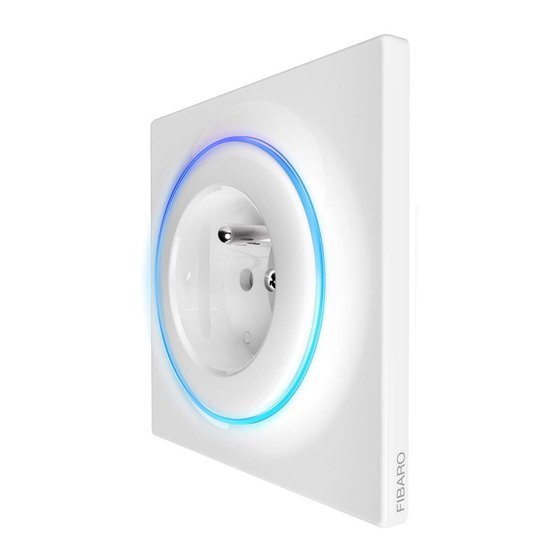
Description and features Description FIBARO Walli Outlet Main features » » » » » DESCRIPTION AND FEATURES... - Page 6 SPECIFICATIONS...
-
Page 7: Before Installation
Installation Before installation Connecting the device in a manner inconsistent with this manual may cause risk to health, life or material damage. Do not Do not Device parts: Preparing for installation INSTALLATION... -
Page 8: Electrical Connection
Electrical connection Notes for the diagram: First assembly When installing with FIBARO covers: INSTALLATION... - Page 9 Changing covers When installing with GIRA covers: When installing with Legrand covers: INSTALLATION...
- Page 10 When installing with Schneider covers: INSTALLATION...
- Page 11 Adding to Z-Wave network Adding (Inclusion) Adding manually manually: Green Magenta ADDING TO Z WAVE NETWORK...
- Page 12 Adding using SmartStart SmartStart using SmartStart: Green Magenta ADDING TO Z WAVE NETWORK...
- Page 13 Removing from Z-Wave network Removing (Exclusion) remove REMOVING FROM Z WAVE NETWORK...
-
Page 14: Operating The Device
Operating the device Controls Button control Visual indications After powering the device: State of the device: Update: Menu: OPERATING THE DEVICE... -
Page 15: Resetting To Factory Defaults
Menu Menu GREEN MAGENTA YELLOW Resetting to factory defaults OPERATING THE DEVICE... - Page 16 Power and energy metering Electric active power Electric energy Resetting consumption memory: POWER AND ENERGY METERING...
- Page 17 Z-Wave range test To test the main controller’s range: Z-Wave range tester signalling modes: Visual indicator pulsing green Visual indicator glowing green Visual indicator pulsing yellow Visual indicator glowing yellow Visual indicator pulsing violet Visual indicator glowing red Z WAVE RANGE TEST...
-
Page 18: Advanced Parameters
Associations Association (linking devices) The device provides the association of 2 groups: 1st association group – “Lifeline” 2nd association group – “Power” Advanced parameters Available parameters: Remember device state Parameter size Default value Available values CONFIGURATION... - Page 19 Overload safety switch Parameter size Default value Available values LED frame – power limit Parameter size Default value Available values LED frame – colour when ON Parameter size Default value Available values CONFIGURATION...
- Page 20 LED frame – colour when OFF Parameter size Default value Available values LED frame – brightness Parameter size Default value Available values CONFIGURATION...
- Page 21 Parameter size Default value Available 0xX0 0xX1 values 0xX2 0xX3 0x0X 0x1X 0x2X 0x4X 0x8X 0xFX Parameter size Default value Available 0xX0 0xX1 values 0xX2 0xX3 0x0X 0x1X 0x2X 0x4X 0x8X 0xFX CONFIGURATION...
- Page 22 Parameter size Default value Available 0xX0 0xX1 values 0xX2 0xX3 0x0X 0x1X 0x2X 0x4X 0x8X 0xFX Parameter size Default value Available 0xX0 0xX1 values 0xX2 0xX3 0x0X 0x1X 0x2X 0x4X 0x8X 0xFX CONFIGURATION...
- Page 23 Parameter size Default value Available 0xX0 0xX1 values 0xX2 0xX3 0x0X 0x1X 0x2X 0x4X 0x8X 0xFX Parameter size Default value Available values Associations – 2nd group Parameter size Default value Available values CONFIGURATION...
- Page 24 Associations – UP threshold Parameter size Default value Available values Associations – UP threshold frame value Parameter size Default value Available values Associations – DOWN threshold Parameter size Default value Available values Associations – DOWN threshold frame value Parameter size Default value Available values...
- Page 25 Power reports – include self-consumption Parameter size Default value Available values Power reports – on change Parameter size Default value Available values Power reports – periodic Parameter size Default value Available values Energy reports – on change Parameter size Default value Available values CONFIGURATION...
- Page 26 Energy reports – periodic Parameter size Default value Available values CONFIGURATION...
- Page 27 Generic Device Class Supported Command Classes Command Class Version Secure Z WAVE SPECIFICATION...
- Page 28 Event Parameter Protection CC Type State Description Hint Meter CC Meter Type Scale Rate Type Precision Size Z WAVE SPECIFICATION...
- Page 29 Parts compatibility Available FIBARO parts Included Parts required for GIRA System 55 (only with non-metalised out- er surface: Standard 55, E2, Event, Event Clear) selected covers* Required FIBARO parts Socket type Parts required for Legrand Céliane selected covers* Required FIBARO parts...
- Page 30 Parts required for Schneider Odace selected covers* Required FIBARO parts Socket type compatible parts or contact our support team. PARTS COMPATIBILITY...
- Page 31 Regulations Legal Notices Declaration of conformity WEEE Directive Compliance REGULATIONS...


Need help?
Do you have a question about the FGWOE-011 and is the answer not in the manual?
Questions and answers