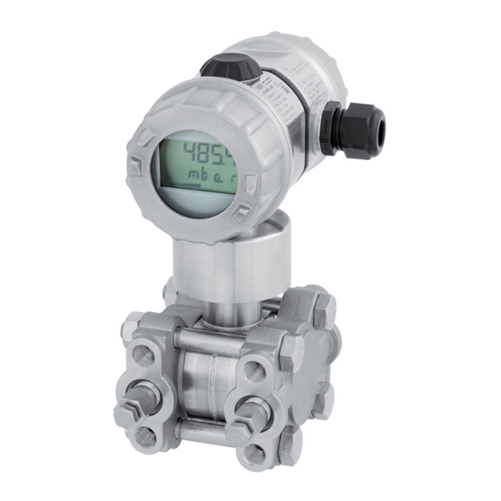
JUMO dTRANS p20 DELTA Operating Instructions Manual
Differential pressure transmitter
Hide thumbs
Also See for dTRANS p20 DELTA:
- Operating manual (88 pages) ,
- Operating instructions manual (64 pages) ,
- Operating manual (84 pages)

Subscribe to Our Youtube Channel
Related Manuals for JUMO dTRANS p20 DELTA


Summary of Contents for JUMO dTRANS p20 DELTA
- Page 1 JUMO dTRANS p20 DELTA Differential pressure transmitter B 403022.0 Operating Instructions 2014-03-18/00519462...
- Page 2 DANGER! Failure of the differential pressure transmitter or an instrument attached to it could possibly lead to dangerous malfunctions! Suitable preventive measures must be in place to prevent this from happening. NOTE! Please read these Operating Instructions before placing the instrument in operation.
-
Page 3: Table Of Contents
Contents Safety information ..............5 Warning symbols ..................5 Note symbols ..................5 General information ............... 7 Scope of application ................7 Scope of delivery ..................7 Instrument identification ............9 Nameplate ....................9 Order details ..................10 Accessories ..................12 Software .................... - Page 4 Contents Instrument with M12 connector ............35 Electrical connection in Ex areas ............37 Operation ................41 Display ....................41 Operation with rotary knob or with setup program ......42 The level concept .................. 43 Maintenance ................. 49 Eliminating errors and faults ..............49 Declaration of Conformity ...........
-
Page 5: Safety Information
1 Safety information Warning symbols DANGER! This symbol indicates that personal injury caused by electrical shock may occur if the respective precautionary measures are not carried out. CAUTION! This symbol in connection with the signal word indicates that damage to assets or data loss will occur if the respective precautionary measures are not taken. - Page 6 1 Safety information...
-
Page 7: General Information
These documents contain information about the set parameters or measured parameters for the relevant pressure transmitter. If the calibration certificate is lost, or if you need another copy, it can be ordered from JUMO. Please indicate the F number of the differential pressure transmitter (manufacturing number, see the nameplate). - Page 8 2 General information CAUTION! The JUMO interface must not be used for instruments with ATEX Ex ia explosion protection! ® These instruments must only be operated with the rotary knob or via the HART interface! PC interface cable Available as an accessory: PC interface cable including USB/TTL converters and two adapters (USB connecting cable), part no.
-
Page 9: Instrument Identification
Nameplate Non-Ex, Enclosure Identification on the enclosure of a differential pressure transmitter that is not suitable for use in hazardous (Ex) areas. Made in Germany www.jumo.net dTRANS p20 DELTA 403022/x-0 TN 12345678 CAL 0...6 bar -1...6 bar DC11.5...36 V 4...20 mA HART F.-Nr: 011925390100930000... -
Page 10: Order Details
3 Instrument identification Order details (1) Basic type 403022 JUMO dTRANS p20 DELTA - Differential pressure transmitter (2) Basic type extension None Special design (3) Explosion protection None ATEX Ex ia (4) Housing Short, stainless steel, with M12 connection Long, stainless steel, with cable gland... - Page 11 3 Instrument identification (13) Measuring system filling medium Silicon oil Halogenized oil (14) Extra codes None Customized setting With GOST R approval With INMETRO approval Free of oil and grease With mounting kit for wall and pipe mounting With TAG number With manufacturer declaration NACE Extended admissible ambient temperature Increased nominal pressure PN 420 bar...
-
Page 12: Accessories
Pressure separator with flange connection to ANSI B 16.5 with sealing lip Form RF 409786 Ex-i Power supply/input isolating amplifier 707530 The PC interface cable is the connection between the JUMO interface of the differential pressure transmitter and the USB interface of a PC. ® The HART modem is the connection between the HART®... -
Page 13: Dimensions
3 Instrument identification Dimensions Type 403022/0-0-1 (short, stainless steel, with M12 connection) 86.5 Type 403022/0-0-2 (long, stainless steel, with plastic cable gland) 63.5 A = Cable gland M20 × 1.5... - Page 14 3 Instrument identification Type 403022/0-0-3 (long, precision casting, with metal cable gland) A = Cable gland M20 × 1.5...
- Page 15 3 Instrument identification For extra code 694 (increased nominal pressure PN420) deep for mounting A = Cable gland M20 × 1.5...
- Page 16 3 Instrument identification...
-
Page 17: Technical Data
410 (4 to 20 mA with HART®) JUMO interface and HART interface The JUMO interface must not be used for instruments with ATEX Ex ia explosion protection! These instruments ® can be operated by the rotary knob or via the HART interface. -
Page 18: Output
4 Technical data Output Analog output for output 405 4 to 20 mA, two wires ® for output 410 4 to 20 mA, two wires with HART 190 ms without damping Step response time T60 Damping adjustable, 0 to 100 s Burden Burden ... -
Page 19: Mechanical Properties
4 Technical data Mechanical properties Process connection Materials Membrane For process connection 20 (Edelstahl) Stainless steel 316L ® For process connection 82 (Hastelloy®) Hastelloy C276, mat. no. 2.4819 For process connection 80 (tantalum) Tantalum Flange Stainless steel 316 Seal PTFE Housing Material For housing 1 (short, stainless steel) -
Page 20: Ambient Conditions
-30 °C. In the range of -40 to -50 °C, the cover with the instrument viewing pane must also be protected against mechanical shock and impact. For details please contact JUMO. Accuracy... -
Page 21: Approvals/Marks Of Conformity
4 Technical data Accuracy at - 0.5 % 0.2 % 0.2 % 20 to +85 °C for r 2 for r 10 for r 5 as % of the set (up to +60 °C) span r × 0.25 % r × 0.02 % r ×... - Page 22 4 Technical data...
-
Page 23: Mounting
The permissible ambient temperature must be maintained (note any possible heat radiation). The JUMO dTRANS p20 differential pressure transmitter can be installed above or under the pressure tapping point. Unscrew the front ring or enclosure cover Plastic cover ring The front ring (1) and rear enclosure cover (2) can be unscrewed. -
Page 24: Rotating The Lcd (Display)
5 Mounting Rotating the LCD (display) Installation position The nominal position of the JUMO dTRANS p20 DELTA differential pressure transmitter is standing and vertical. Depending on the specific features of the measuring point, the differential pressure transmitter can be installed in any other location. The LCD display can be rotated in 90°... -
Page 25: Rotating The Enclosure
5 Mounting Unscrew the front ring, see section 5.2 "Unscrew the front ring or enclosure cover", page Pry out the electronics module with a narrow (small) screwdriver. Rotate the electronics module to the preferred position (in 90° increments) and reinsert it. Screw on the front ring finger-tight. -
Page 26: Pressure Connection
5 Mounting Pressure connection Seals Operating conditions (for example material compatibility) must be considered when selecting the seal. Check for leaks If the pressure connection is made, it must be checked for leaks. DANGER! Improper operation of shut-off fittings can result in bodily injury and significant material damage! Follow the specified order for opening and closing valves! For use in toxic media the device must not be vented! -
Page 27: Bracket For Wall Und Pipe Mounting
5 Mounting Bracket for wall und pipe mounting (Part no. 00543777) Mounting example... -
Page 28: Level Measurement With Diaphragm Seals
5 Mounting Level measurement with diaphragm seals For DP level measurement of liquids in a closed tank with diaphraghm seals, the DP transmitter has to be mounted according to the following graphic. • PLUS input side at top • MINUS input side at bottom •... - Page 29 5 Mounting 5.7.2 Configuration Configuration without level input (blind setting) Range Start (4 mA): = H × Set P5 [mbar] × g × 0.01 Range End (20 mA): = (H × × Set P6 [mbar] ) × g × 0.01 Explanation: [mm] = vertical spacing of diaphragm seals...
-
Page 30: Assembly In The Explosion Area
5 Mounting Assembly in the explosion area Hazardous (Ex) area Zone 0/20 Non-hazardous area ® Burden (optional for HART interface) Power supply device with isolating converter for connecting explosion-protected transmitters... -
Page 31: Installation
6 Installation Installation instructions DANGER! The electrical connection must only be performed by qualified personnel! Ground the instrument! If contact with live parts is possible when working on the device, it must be completely disconnected from the electrical supply. Electromagnetic compatibility meets the requirements of EN 61326. The transmitter is suitable for use in SELV or PELV current circuits according to protection rating 3. -
Page 32: Instrument With Cable Gland
6 Installation Instrument with cable gland General information DANGER! For connection to instruments in Ex areas see section "Electrical connection in Ex areas", page 37! • Permissible cable diameter for instruments with cable gland made of: 6 to 12 mm •... - Page 33 6 Installation Connection Unscrew the housing cover from behind, see section 5.2 "Unscrew the front ring or enclosure cover", page 23. To connect the connecting cables, see the following illustration. Pin configuration Connection Pin configuration Power supply 1 L+ for non Ex version DC 11.5 to 36 V 2 L- for Ex version DC 11.5 to 28 V...
- Page 34 6 Installation Operation and test HART - HART + Test - Test + Total burden: Burden (U -11.5 V) ÷ 0.022 A; ® in addition: min. 250 , max. 1100 for HART Display or recording instrument, controller, PLC, etc. Power supply: for non Ex version DC 11.5 to 36 V for Ex version DC 11.5 to 28 V...
-
Page 35: Instrument With M12 Connector
6 Installation Instrument with M12 connector DANGER! For connection of the device in an Ex area see section "Electrical connection in Ex areas", page 37! Connect the device to ground using pin 4 of the device connector, see section "Pin configuration", page 36! A suitable connection is provided by a •... - Page 36 6 Installation Pin configuration Connection Color configuration assignment Power supply 1 L+ Brown for non Ex version DC 11.5 to 36 V 3 L- Blue for Ex version DC 11.5 to 28 V Output Brown 4 to 20 mA two wires Blue Impressed current 4 to 20 mA in power supply...
-
Page 37: Electrical Connection In Ex Areas
6 Installation Electrical connection in Ex areas General information Applicable requirements must be followed for the electrical connection, especially in a potentially explosive atmosphere: • Regulation concerning electrical systems in areas with an explosion hazard (Elex V) • Determination for project planning, selecting and setting up electrical systems in areas with an explosion hazard (IEC 60079-14:2007) •... - Page 38 DANGER! ® Only the HART modem may be used in explosion-protected areas! The JUMO interface must not be used! The power supply must be intrinsically safe and must not exceed the following maximum values: : DC 28 V : 93 mA...
- Page 39 6 Installation 6.4.1 Connection diagram "EX" (10) Hazardous (Ex) area Zone 0/20 Non-hazardous area ® (U Burden for HART -11.5 V) ÷ 0.022 A in addition min. 250 , max. 1100 The current limiting resistor integrated into the power supply device must be included in the calculations in this case.
- Page 40 6 Installation...
-
Page 41: Operation
7 Operation Display Socket for JUMO setup interface (behind a cap) Measured value Unit of measure Overrange Output current (4 to 20 mA) Underrange... -
Page 42: Operation With Rotary Knob Or With Setup Program
The setup program can optionally access the instrument through the following interfaces: • JUMO setup interface. The PC interface cable with USB/TTL converter (USB connecting cable) is required to connect the PC with the instrument, part no. 00456352. -
Page 43: The Level Concept
7 Operation Rotate and press Rotate Select parameters or adjust values. Press Confirm parameters or values. The level concept Two levels Operation is on two levels: NOTE! After the instrument is turned on, it is on the display level. You can go to the parameter level through the following operation. - Page 44 7 Operation 7.3.1 The display level The measured pressure and other parameters are shown on the display level. The output current is shown as a percentage in a bar diagram on the third line. It is not possible to change parameters on the display level! Action Display Explanation...
- Page 45 7 Operation 7.3.2 The parameter level Instrument parameters can be displayed and changed on the parameter level. Action Display Explanation Selection (example) Reset by P min Saved minimum pressure > 3 seconds Reset by P max Saved maximum > 3 seconds pressure 0.01 to 1.00 to 99.99 P0 Den...
- Page 46 7 Operation Action Display Explanation Selection (example) Nominal measuring range P6 RE "Range end" end of measurement Current pressure P7 Zero Zero-point adjustment 3.60 to 4.00 to 21.60 mA P8 mA Current sensor ErLo = 3.6 mA P9 Err ErHi = 21.6 mA Current in case of error LASt...
- Page 47 7 Operation Action Display Explanation Selection (example) -9999 to 0 to 9999 P16 SCS Scaling start -9999 to 100 to 9999 P17 SCE Scaling end P18 SCD Auto = Automatic 0 = No places after decimal point Scaling decimal point 1 = 1 place after decimal point 2 = 2 places after decimal point 3 = 3 places after decimal point...
- Page 48 7 Operation...
-
Page 49: Maintenance
8 Maintenance Eliminating errors and faults Error/fault Possible cause Remedy Display: None No power supply Turn on the power supply Instrument faulty Send the instrument to the supplier for repairs Display: Overrange, overpressure Bring the pressure back into the measuring range or adjust the Display: Underrange, measuring range... - Page 50 8 Maintenance...
-
Page 51: Declaration Of Conformity
9 Declaration of Conformity... - Page 52 9 Declaration of Conformity...
-
Page 53: Type Examination Certificate
10 Type Examination Certificate... - Page 54 10 Type Examination Certificate...
- Page 55 10 Type Examination Certificate...
- Page 56 10 Type Examination Certificate...
- Page 57 10 Type Examination Certificate...
- Page 58 10 Type Examination Certificate...
- Page 60 JUMO GmbH & Co. KG JUMO Instrument Co. Ltd. JUMO Process Control, Inc. Street address: JUMO House 6733 Myers Road Moritz-Juchheim-Straße 1 Temple Bank, Riverway East Syracuse, NY 13057, USA 36039 Fulda, Germany Harlow - Essex CM20 2DY, UK Phone:...
Need help?
Do you have a question about the dTRANS p20 DELTA and is the answer not in the manual?
Questions and answers