JUMO dTRANS p02 Operating Manual
Pressure transmitter
Hide thumbs
Also See for dTRANS p02:
- Operating instructions manual (64 pages) ,
- Operating instructions manual (64 pages)

Related Manuals for JUMO dTRANS p02


Summary of Contents for JUMO dTRANS p02
- Page 1 JUMO dTRANS p02 Pressure Transmitter B 404385.0 Operating Manual V1.00/EN/00365643...
- Page 3 Contents General information ............... 5 Application ....................5 Safety information ..............7 Warning signs ..................7 Reference signs ..................7 Delivery package ..............9 Instrument identification ............. 11 Nameplate ..................... 11 Order details ..................12 Accessories ..................13 Dimensions/details ................14 Dimensions: "non-flush pressure connections"...
- Page 4 Contents Measuring the gauge pressure ............. 37 Adjustment options .............. 41 The level concept .................. 41 Sequence for keypad operation ............42 Display level ..................43 Parameter level ..................44 Detailed explanations ................47 Opening the instrument ............51 10.1 Unscrewing the bezel ring or housing cover ........
-
Page 5: General Information
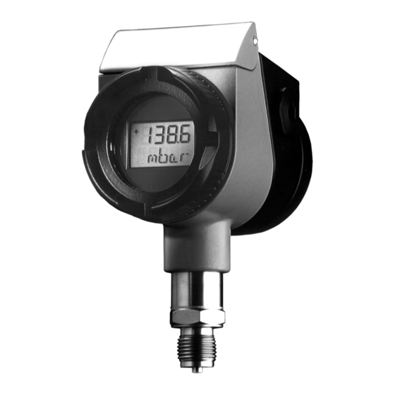
Application General The type JUMO dTRANS p02 is used to measure the pressure of corrosive and non-corro- sive gases, vapors and liquids. The pressure transmitter uses the piezo-resistive effect to make the measurement. The output signal is a proportional DC current which is linearly pro- portional to the input pressure. - Page 6 1 General information...
-
Page 7: Safety Information
2 Safety information Warning signs DANGER! Failure to follow this manual or failure to follow them precisely may result in injury! CAUTION! Failure to follow this manual or failure to follow them precisely may result in damage to instruments or data! Reference signs NOTE! This sign is used to draw special attention to something. - Page 8 2 Safety information...
-
Page 9: Delivery Package
® ® The HART modem serves to connect the JUMO dTRANS p02 to a PC. The HART modem is available on request, at extra cost, part no. 00345666. Power supply A supply unit with a supply isolator is available on request, at extra cost, part no. 00577948. - Page 10 3 Delivery package...
-
Page 11: Instrument Identification
4 Instrument identification Nameplate Nameplate on a pressure transmitter without approval for use within the hazardous (Ex) area. Nameplate on a pressure transmitter with approval for use within the hazardous (Ex) area. -
Page 12: Order Details
4 Instrument identification Order details (1) Basic type 404385/0 JUMO dTRANS p02 - Pressure transmitter 404385/1 JUMO dTRANS p02 - Pressure transmitter with Ex protection Ex II 1/2 G Ex ia IIC T6 Ga/Gb 404385/4 JUMO dTRANS p02 - Pressure transmitter for increased temperature of medium up to 200 °C... -
Page 13: Accessories
Suitable process connection adapter, see data sheet 409711. Please specify in plain text. Order code Order example 404385/0 Accessories Description Part no. Setup program for all instruments in the JUMO dTRANS p02 series 00365072 ® HART modem USB 00443447 Data Sheet Ex-i Power supply/input isolating amplifier... -
Page 14: Dimensions/Details
4 Instrument identification Dimensions/details G 1/2 (10) 1/2” pipe NTS 527 Cover for electrical connection PE connection Cover flap (keypad underneath) Bezel Process connection Electrical connection, M 20 × 1.5 cable gland Blanking plug (electrical connection Electrical connection, or instrument mounting possible) Harting connector Han 7D/Han 8D (8U) LCD display (10) Special version "Process connection":... -
Page 15: Dimensions: "Flush Pressure Connections
4 Instrument identification Dimensions: "flush pressure connections" 604/606 604 / 606 taper connection with slotted ring nut Kegelstutzen mit Nutüberwurfmutter 613/616 to DIN 11 851 613 / 616 nach DIN 11 851 to DIN 32676 nach DIN 32 676 32 a/f SW 32 3/4"... - Page 16 4 Instrument identification...
-
Page 17: Technical Data
5 Technical data Range Start and end of range can be adjusted continuously within the measuring range. The measu- ring span should not go below 10 % of the nominal range. v Chapter 4.1 "Nameplate", page 11; For setting the measurement start or span: v "Measurement start, blind setting", page 47 v "Measurement span, blind setting", page 48 Mechanical shock... - Page 18 5 Technical data Explosion protection II 1/2 G Ex ia IIC T6 Ga/Gb, to EN 60079-0, EN 60079-11 and EN 60079-26 EC-Type Examination Certificate PTB 98 ATEX 2194 Permissible ambient temperature Temperature class +85 °C +75 °C +60 °C...
-
Page 19: Mounting
Open cover flap The cover flap can be opened with a coin. The keys for operating the JUMO dTRANS p02 are underneath the cover flap. For details on the setting options see: v Chapter 9.1 "The level concept", page 41ff. -
Page 20: Mounting By The Pressure Connection
6 Mounting Operating position The normal operating position of the JUMO dTRANS p02 pressure transmitter is vertically upright. Depending on the conditions of the measurement site, the pressure transmitter can also be mounted in a different orientation. In accordance with the required operating position, the LCD can be rotated in 90°... -
Page 21: Pressure Connection
6 Mounting Pressure connection Seals Seals to EN 837 or DIN 16 258 may be used. Tightening torque 200 Nm max. The correct tightening torque depends on the size, material and shape of the seal that is used, as well as on the pressure connection of the pressure transmitter. Check for tightness After establishing the pressure connection, it must be checked for tightness. - Page 22 6 Mounting...
-
Page 23: Installation
7 Installation 7 Installation Electrical connection NOTE! Ground the device! TEST HART Unscrew the cover from the housing. v Chapter 10.1 "Unscrewing the bezel ring or housing cover", page 51 General notes • Cable diameter 6 to 12 mm. • Conductor cross-section up to 1.5 mm ... - Page 24 7 Installation 7.1.1 Connection with screw terminals/Harting connector Han 7D/ Han 8D (8U) Connection diagram TEST HART Screw terminals Harting connector Connection Terminals Supply 1 L+ 11.5 to 36 V DC 2 L- 11.5 to 30 V DC for intrinsically safe version Output 1 L+ proportional current...
-
Page 25: Testing The Output Signal
7 Installation Connection Supply voltage 11.5 to 36 VDC TEST HART Burden Burden (U - 11.5 V 0.022 A min. 250 , max. 1100 ® Burden with HART Unscrew the housing cover v Chapter 10.1 "Unscrewing the bezel ring or housing cover", page 51. Insert the cable through the cable gland. - Page 26 7 Installation ® HART communication between PC and transmitter Supply voltage Pressure transmitter Burden up to 15 transmitters JUMO dTRANS p02 11.5 — 36 V DC (multidrop mode) ® HART modem PC or notebook Setup program Burden (U - 11.5 V)/0.022 A ®...
- Page 27 7 Installation ® Testing the HART communication ® HART communicator ® HART modem Supply voltage 11.5 to 36 V DC TEST HART Burden Burden (U - 11.5 V)/0.022 A ® min. 250 , max. 1100 Burden with HART NOTE! Test connection via faston connectors 2.8 mm ×...
-
Page 28: Electrical Connection In The Hazardous (Ex) Area
7 Installation Electrical connection in the hazardous (Ex) area General The appropriate regulations must be observed when making the electrical connection; inside the area with an explosion hazard this is, in particular: • The regulations concerning electrical equipment in areas with an explosion hazard (Elex V). - Page 29 7 Installation 7.5.1 Connection diagram "EX" Control room Site intrinsically not intrinsically safe safe circuit connections (2) +(3) Supply voltage TEST HART Output Other units ® HART notebook ® ® modem HART communicator HART communicator intrinsically safe intrinsically safe RS-232-C (1) Supply unit with isolating transformer for connecting a transmitter with explosion protec- tion modem: 250 ...
- Page 30 7 Installation...
-
Page 31: Commissioning
8 Commissioning Characteristic Output signal and display Example: Nominal range 0 to 600 mbar. Range setting 50 to 450 mbar. Output current [mA] Fault current Saturation Saturation Fault current (21.5 or 3.85) (low) (high) (21.5 or 3.85) 21.50 20.00 4.00 Pressure 3.85 [mbar]... -
Page 32: Self-Test
8 Commissioning Self-test Active After the supply has been switched on, the pressure transmitter carries out a self-test. If the result of the self-test is positive, the display that was most recently selected at the dis- play level will be shown after approx. 20 seconds (on new pressure transmitters, the display "pressure with unit"). - Page 33 8 Commissioning Error On over/underrange, an error signal appears, v see below v Chapter12.1 "Trouble-shooting", page 55...
-
Page 34: Measuring The Absolute Pressure
8 Commissioning Measuring the absolute pressure Gases Transmitter below Transmitter above the pressure tapping the pressure tapping (exception) (standard arrangement) Transmitter Shut-off fitting 2A shut-off valve to process 2B shut-off valve for test connection Pressure line Shut-off valve Shut-off valve Condensation vessel Purge valve Pressure application... - Page 35 8 Commissioning Vapors Transmitter Shut-off fitting 2A shut-off valve to process 2B shut-off valve for test connection Pressure line Shut-off valve Blow-down valve Pressure equalization reservoir Pressure application Initial state: all valves closed. Operate the shut-off fittings in the following order: Open shut-off valve (4) at the pressure tapping.
- Page 36 8 Commissioning Liquids Transmitter Shut-off fitting 2A shut-off valve to process 2B shut-off valve for test connection Pressure line Shut-off valve Blow-down valve Pressure application Initial state: all valves closed Operate the shut-off fittings in the following order: Open shut-off valve (4) at the pressure tapping. Open shut-off valve (2A).
-
Page 37: Measuring The Gauge Pressure
8 Commissioning Measuring the gauge pressure Gases Transmitter above Transmitter below the pressure tapping the pressure tapping (standard arrangement) (exception) Transmitter Shut-off fitting 2A shut-off valve to process 2B shut-off valve for test connection or vent screw Pressure line Shut-off valve Shut-off valve Condensation vessel Purge valve... - Page 38 8 Commissioning Vapors Transmitter Shut-off fitting 2A shut-off fitting to process 2B shut-off fitting for test connection or vent screw Pressure line Shut-off valve Blow-down valve Pressure equalization reservoir Pressure application Initial state: all valves closed Operate the shut-off fittings in the following order: Open shut-off valve (2B).
- Page 39 8 Commissioning Liquids Transmitter Shut-off fitting 2A shut-off valve to process 2B shut-off valve for test connection or vent screw Pressure line Shut-off valve Blow-down valve Pressure application Initial state: all valves closed Operate shut-off fitting in the following order: Open shut-off valve (2B).
- Page 40 8 Commissioning...
-
Page 41: Adjustment Options
Two levels In order to make the operation of the pressure transmitter simple and transparant, the func- tions of the JUMO dTRANS p02 have been divided into two levels. Both levels can be accessed from the keypad of the transmitter. -
Page 42: Sequence For Keypad Operation
9 Adjustment options Sequence for keypad operation Layout Display level Parameter level after complete run or press "P" key for > 3 sec or pause for > 120 sec (Pmin) Reset Pressure min. pressure with dim. unit (P7) > 1 s (Pmax) Zero adjustment... -
Page 43: Display Level
9 Adjustment options Display level NOTE! After switching on the pressure transmitter, the last display that was selected will be shown at the display level. Sequence Action Function Display (Example) Display of pressure with dimensional unit Display of pressure value and sensor temperature in the units selected Display of the stored maximum pressure Display of the stored minimum pressure... -
Page 44: Parameter Level
9 Adjustment options Parameter level Action Function Display Possible with keys "Detailed explanations", (Example) setting page 47ff. Reset the stored reset "Peak-readingpointer", minimum page 47. > 2 pressure > 1 seconds second Reset the stored reset "Peak-readingpointer", maximum page 47. >... - Page 45 9 Adjustment options Action Function Display Possible with keys "Detailed explanations", (Example) setting page 47ff. Display or set -110 % to "Measurement start, oder measurement +110 % blind setting", page 47. start > 1 (blind setting) -10 to second +110 % of nominal range Display or set...
- Page 46 9 Adjustment options Action Function Display Possible with keys "Detailed explanations", (Example) setting page 47ff. Display and "Keys inhibited", page oder set key inhibit no inhibit > 1 all inhibited second LALL: all inhibited (adjustable via setup program only) all inhibited except measurement start and end...
-
Page 47: Detailed Explanations
9 Adjustment options Detailed explanations Peak-readingpointer Minimum and maximum pressures are saved. Both values can be individually displayed and deleted. NOTE! If the damping is set to 0.0 sec, minimum and maximum pressures will not be saved. v "Detailed explanations", page 47 If the damping is 0.0sec, or after a reset of the display, "- - - - -"... - Page 48 9 Adjustment options The necessary setting for the measurement start is derived as follows: Nominal range: 0 to 25 bar Meas. start required: 5 bar, corresponding to 20 % of the nominal range Setting: 20 % Measurement span, blind setting The measurement span can be set in % of the nominal measurement range.
- Page 49 9 Adjustment options Keys inhibited To prevent an unauthorized modification of parameters, some or all of the parameters can be inhibited. NOTE! To remove an inhibit (LA, L0, LS), the key must be pressed for longer than 5 seconds in the display “Output current in fault situation”...
- Page 50 9 Adjustment options Unit of temperature display The display unit of the measured sensor temperature can be selected as: • °C • °F...
-
Page 51: Opening The Instrument
10 Opening the instrument 10.1 Unscrewing the bezel ring or housing cover The bezel ring and the rear housing cover can be unscrewed. Housing cover Bezel ring Open with a screwdriver Close by hand without any tools... - Page 52 10 Opening the instrument...
-
Page 53: Rotating The Instrument
11 Rotating the instrument 11.1 Rotating Rotating the LCD display Depending on the operating position required, the LCD display can be rotated in steps of 90°. Unscrew the bezel ring. v "Unscrewing the bezel ring or housing cover", page 51. Use a small-bladed screwdriver to carefully push out the catch of the LCD fixing and lever out the display board. - Page 54 11 Rotating the instrument...
-
Page 55: Maintenance
12 Maintenance 12.1 Trouble-shooting Error/fault Possible cause Remedy Display: none no supply voltage switch on supply instrument faulty send instrument to supplier for repair Display: overrange, bring pressure back to within range, or excessive pressure adjust range Display: underrange, bring pressure back to within range, or pressure too low adjust range Display:... - Page 56 12 Maintenance keys inhibited reset key inhibit v "Keys inhibited", page 49. key not responding instrument faulty send instrument to supplier for repair You can find the supplier addresses on the back page of this operating manual.
-
Page 57: Appendix
13 Appendix 13.1 Settings NOTE! Individual settings can be recorded in this table. Function LCD display Factory Customer’s setting setting Min. value (peak-reading pointer) P min – not adjustable Max. value (peak-reading pointer) P max – not adjustable Density correction 1.000 Dimensional unit bar or mbar... - Page 58 13 Appendix...
-
Page 59: Declaration Of Conformity
TÜV NORD CERT GmbH, Am TÜV 1, 30519 Hannover, Germany Kennnummer 0044 Identification No. 0044, N° d'identification 0044 / Company / Société Firma Aussteller: JUMO GmbH & Co. KG, Fulda Fulda Issued by: / Etabli par: Ort, Datum: Fulda, 2015-10-22 Place, date: / Lieu, date:... - Page 60 14 Declaration of Conformity...
-
Page 61: Type Examination Certificate
15 Type Examination Certificate... - Page 62 15 Type Examination Certificate...
- Page 63 15 Type Examination Certificate...
- Page 64 15 Type Examination Certificate...
- Page 65 15 Type Examination Certificate...
- Page 66 15 Type Examination Certificate...
- Page 67 15 Type Examination Certificate...
- Page 68 15 Type Examination Certificate...
- Page 69 15 Type Examination Certificate...
- Page 70 15 Type Examination Certificate...
Need help?
Do you have a question about the dTRANS p02 and is the answer not in the manual?
Questions and answers