
Subscribe to Our Youtube Channel
Related Manuals for JUMO HART dTRANS p20 Ex d


Summary of Contents for JUMO HART dTRANS p20 Ex d
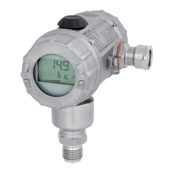
- Page 1 JUMO dTRANS p20 Ex d Process pressure transmitter explosion-protected, explosion-proof enclosure Operating Manual 40302600T90Z001K000 V9.00/EN/00556401/2022-10-31...
-
Page 3: Table Of Contents
Contents Contents Safety information..........5 Hazardous materials . - Page 4 Contents Operation ........... 41 Display .
-
Page 5: Safety Information
Safety information 1 Safety information General This manual contains information that must be observed in the interest of your own safety and to avoid material damage. This information is supported by symbols which are used in this manual as indicated. Please read this manual before starting up the device. - Page 6 1 Safety information...
-
Page 7: General Information
General information 2 General information DANGER! The device is suitable for measuring pressure in gases and liquids without solids content. In the SIL version (functional safety), this device is used in safety-related systems for minimum, maximum and area monitoring that fulfil the requirements of the series of standards IEC 61508:2010. -
Page 8: Scope Of Delivery
Graphical view of temperature and pressure • Detailed diagnostic messages • Display of the complete order code and the device configuration (for follow-up orders) The setup program accesses the device via • the JUMO interface (standard) or • the HART® interface (optional) - Page 9 Available as an accessory: PC interface cable with USB/TTL converter and two adapters (USB transmit- ter cable), part no. 00456352. The device can be connected to a PC's USB port via the JUMO interface with the PC interface cable. HART® modem (option) Available as an accessory: HART®...
- Page 10 2 General information...
-
Page 11: Identifying The Device Version
Identifying the device version 3 Identifying the device version Nameplate Housing Sample identification marking on the device housing. Part number Fabrication number Output signal Voltage supply Nominal measuring range Werkseinstellung Nennmessbereich Type SIL-Ausführung Date of manufacture The date of manufacture (year and calendar week) of the device is encoded in the manufacturing num- ber. -
Page 12: Order Details
3 Identifying the device version Order details Basic type 403026 JUMO dTRANS p20 Ex d - process pressure transmitter with flameproof enclosure Basic type extension None Special version Display None With display Operation None With control knob Input – nominal measuring range -600 to +600 mbar relative pressure -1 to +2.5 bar relative pressure... - Page 13 3 Identifying the device version NiMo Measuring system, filling medium Without Silicon oil (10) Extra codes None Customer-specific factory setting GOST/EAC approval Wetted, electrolytically polished parts Choke in the pressure channel Oil and grease free Enlarged pressure channel TAG number NACE manufacturer's declaration Expanded admissible ambient temperature Only available with display 1.
-
Page 14: Accessories
409784 Diaphragm seal with flange connection according to ANSI B 16.5 with sealing strip form RF 409786 The PC interface cable is the connection between the JUMO interface of the differential pressure transmitter and the USB interface of a PC. -
Page 15: Dimensions
3 Identifying the device version Dimensions Kabelverschraubung M20 × 1,5 3.5.1 Process connections G 1/2 1/2-14 NPT 1/2-14 NPT internal SW 27 1/2-14 NPT 1/2-14 NPT G 1/2 G 3/4 M20 (× 1.5) with pin SW 32 G 3/4 M 2 0 x 1 , 5... - Page 16 613 and 616 Taper socket with grooved union nut according to DIN 11851 Clamp according to DIN 32676 Tank connection with grooved JUMO PEKA union nut DN 25 SW 27 RD52 x 1/6 Dimensions of the process connections 604, 606, 613, and 616 Connection Ø...
-
Page 17: Technical Data
HART® interface HART®) optional; SIL version only available with display The JUMO interface may not be used in a potentially explosive area! In such a case the device can be operated via the rotary knob or the HART® interface. -
Page 18: Input
4 Technical data Input Relative pressure Nominal measuring -600 to +600 mbar -1 to +2.5 bar -1 to +4 bar -1 to +10 bar range Overload capability 6 bar 15 bar 30 bar 60 bar Burst pressure 12 bar 30 bar 60 bar 100 bar Relative pressure... -
Page 19: Mechanical Features
(tank connection with grooved union nut) For process connection 997 FDA compliant: FPM, VMQ, EPDM as an option, see data sheet 409711 (JUMO PEKA) For all other process connections No seal Measuring membranes For material lid 20 (stainless steel) 1.4542 for -1 to +250 bar relative pressure (measuring range 508) and... -
Page 20: Environmental Influences
30 °C operation of the device not possible. In the range from -40 to -50 °C the device must be permanently in operation. Furthermore, the lid with the device inspection glass must additionally be protected against mechanical impact and shock effects. Please contact JUMO for further details. -
Page 21: Accuracy
4 Technical data Accuracy Including non-linearity, hysteresis, non-repeatability, zero point and final value deviation (corresponds to measurement deviations according to IEC 61298-2), calibrated at vertical installation position with the process connection at the bottom Relative pressure Nominal measuring -600 to +600 mbar -1 to +2.5 bar -1 to +4 bar -1 to +10 bar... - Page 22 4 Technical data Absolute pressure Nominal measuring 0 to 600 mbar 0 to 2.5 bar 0 to 4 bar 0 to 10 bar range Default 0 to 600 mbar 0 to 2.5 bar 0 to 4 bar 0 to 10 bar measuring range Smallest MSP 60 mbar...
-
Page 23: Approvals And Approval Marks
Inspection basis TR ZU 012/2011 (Ex) Valid for Extra code 226 Testing agency exida Certificates/certification numbers JUMO 2203088 C001 Inspection basis IEC 61508:2010-1/-2/-3 Valid for Basic type extension 2 For the special conditions for use, the examination certificate must be observed. - Page 24 4 Technical data...
-
Page 25: Mounting
Mounting 5 Mounting Before mounting DANGER! Depressurize the plant before installing the device! The device may only be opened in the potentially explosive area when disconnected from the power supply! NOTE! Select a freely accessible and low-vibration installation location, preferably near the measuring point. Ensure that the admissible ambient temperature is adhered to (take possible heat radiation into ac- count). -
Page 26: Rotating The Lcd (Display)
5 Mounting Rotating the LCD (display) Installation position The rated position of the device is vertically upright. Depending on the conditions of the measuring point, the device can be installed in any other position. The LCD display can be rotated in 90° steps depending on the desired installation position. 1. -
Page 27: Rotating The Housing
5 Mounting Rotating the housing The housing can be rotated ±160°. 1. Loosen the threaded pin using a 1.5 mm hex wrench (1/2 turn is sufficient). 2. Rotate the housing to the desired position. 3. Screw on the threaded pin again until it is tight. -
Page 28: Pressure Connection
5 Mounting Pressure connection Seals Operating conditions (for example material compatibility) must be considered when selecting the seal. Tightening torques Maximum 200 Nm The correct tightening torque depends on the size, material and shape of the seal that is used and the pressure connection of the device. -
Page 29: Measuring The Relative Or Absolute Pressure
5 Mounting Measuring the relative or absolute pressure Gases Transmitter above the pressure sensing point Transmitter below the pressure sensing point (normal arrangement) (exception) Transmitter Shut-off valve 2 A shut-off valve for processing 2 B shut-off valve for test connection Pressure pipe Shut-off valve Shut-off valve (optional) - Page 30 5 Mounting Steam Transmitter Shut-off valve 2 A shut-off valve for processing 2 B shut-off valve for test connection Pressure pipe Shut-off valve Blow-off valve Compensating vessel Pressurization Start position: all valves closed Operate shut-off valves in the following order: 1.
- Page 31 5 Mounting Liquids Transmitter Shut-off valve 2 A shut-off valve for processing 2 B shut-off valve for test connection Pressure pipe Shut-off valve Blow-off valve Compensating vessel Pressurization Start position: all valves closed Operate shut-off valves in the following order: 1.
-
Page 32: Bracket For Wall And Pipe Mounting
5 Mounting Bracket for wall and pipe mounting Mounting example (Part no. 00597711) -
Page 33: Level Measurement With Or Without A Pressure Separator
5 Mounting Level measurement with or without a pressure separator The device is ideally suited for level measurements in open containers. Mounting without a pressure separator It is a good idea to mount cutters and drain valves in order to catch and remove deposits and pollutants. This makes it possible to remove the device even when the tank is full. -
Page 34: Assembly In The Explosion Area
5 Mounting tank. Pay attention to the tolerability of the filling oil with the requirements of the medium. For example, only filling oils that do not pose a health risk may be used in the food industry. Assembly in the explosion area Hazardous area Zone 0/20 Hazardous area Zone 1/21 Non-hazardous area... -
Page 35: Installation
0.25 to 0.75 mm (for rigid or flexible cable) DANGER! The JUMO interface must not be used in the explosion-proofed area! The device‘s voltage supply must be intrinsically safe and must not exceed the following maximum values: DC 12 to 36 V... - Page 36 6 Installation NOTE! Connecting the HART® communicator or the HART® modem is optional. A minimum burden must be present on the signal circuit in order to facilitate error-free communication, see the previous pages.
-
Page 37: Connection Diagram "Ex
6 Installation 6.1.1 Connection diagram "Ex" Hazardous area Zone 0/21 Hazardous area Zone 1/21 Non-hazardous area Burden for HART® ≤ (U -12 V) ÷ 0.022 A; additional: min. 250 Ω, max. 1100 Ω Voltage supply Indicating device or recorder, controller, PLC, etc. Additional devices HART®... -
Page 38: Device With Cable Gland
6 Installation Device with cable gland General information • Cables or lines must be suitable for the environmental influences • Cable diameters of 7.5 to 11.9 mm are admissible • Max. conductor cross section of 1.5 mm • Lay the signal lines isolated from cables with a voltage of > 60 V •... - Page 39 6 Installation Connection 1. To unscrew the rear housing lid, see chapter 5.2 "Unscrew the front ring or case lid", Page 25 2. Ground the device. 3. For connecting the connecting cables, see the following figure: CAUTION! Once electrical connection is complete, re-tighten the locking screw of the housing cover! Connection Terminal assignment Voltage supply...
- Page 40 6 Installation Operation and testing HART - HART + Test - Test + Total burden: Burden ≤ (U -12 V) ÷ 0.022 A; for HART® additional: min. 250 Ω, max. 1100 Ω Indicating device or recorder, controller, PLC, etc. Voltage supply DC 12 to 36 V HART®...
-
Page 41: Operation
Operation 7 Operation Display Socket for JUMO setup interface (behind a cover) Measured value Measuring unit Overrange Percentage control of the measuring range Underrange... -
Page 42: Operation With Rotary Knob Or With Setup Programm
The setup program can address the device via the following interfaces: • JUMO setup interface The PC interface cable with USB/TTL converter (USB transmitter cable) is required to connect the PC to the device, part no. 00456352 •... -
Page 43: The Level Concept
7 Operation The level concept Two levels Operation is on two levels: NOTE! After the device is turned on, it is on the display level. You can go to the parameter level through the following operation. Display level (Normal display) >... -
Page 44: The Display Level
7 Operation 7.3.1 The display level The measured pressure and other values are displayed at the display level. The output current is shown in % as a bar chart in the third line of the display. It is not possible to change parameters at the display level! Action Display Explanation... -
Page 45: The Parameter Level
7 Operation 7.3.2 The parameter level The device parameters can be displayed and changed at the parameter level. Action Display Explanation Selection (example) P min Reset by Stored minimum > 3 seconds pressure P max Reset by Stored maximum > 3 seconds pressure P0 Den 0.01 to 1.00 to 99.99... - Page 46 7 Operation Action Display Explanation Selection (example) P6 RE Nominal measuring range "Range end" Measuring range Upper range value P7 Zero Current pressure Zero point adjust- ment P8 mA 3.60 to 4.00 to 21.60 mA Current generator P9 Err ErLo = 3.6 mA ErHi = 21.6 mA Current in case of LASt = last value...
- Page 47 7 Operation Action Display Explanation Selection (example) P16 SCS -9999 to 0 to +9999 Scaling start „Scaling start“ P17 SCE -9999 to 100 to +9999 Scaling end „Scaling end“ P18 SCD Auto = automatic 0 = no decimal place Decimal place scal- 1 = 1 decimal place 2 = 2 decimal places „Scaling decimal...
- Page 48 7 Operation...
-
Page 49: Configuration
Configuration 8 Configuration Data flow diagram... -
Page 50: Description Of The Possible Configurations
8 Configuration Description of the possible configurations P0 Den Density correction Configuration of the density of the medium to be measured This may, for example, be relevant for the level measurement in order to display the correct filling height from the measured pressure. CAUTION! The set value should remain at the value 1 and should be changed in exceptional cases. - Page 51 8 Configuration CAUTION! No further density corrections may be configured. No other values may be entered under P2 mA. P6 RE Measuring range upper range value Configuration of the device (measuring range) without pressure specification Any values can be entered here as the upper range value. It is important when, for example, a differential pressure measurement with a diaphragm seal is attached to an application (e.g.
- Page 52 8 Configuration P11 Chr Characteristic line This point is not relevant for relative/absolute pressure measurement and should therefore not be configured. It can be used with the differential pressure measurement to implement a flow measurement. With P11, the characteristic line of the preset value Lin = pressure proportional can be re- configured to a square root extraction characteristic line SLin or SOff = flow proportional.
- Page 53 8 Configuration P15 Off Pressure value offset The offset value of the pressure value (relative or absolute pressure) is shown in figures here (e.g. after the zero point adjustment). The values listed there should only be corrected in exceptional cases as it is possible to manually readjust an offset there. Please contact the manufacturer for this.
-
Page 54: Level Measurement Configuration With A Pressure Specification - Recommended (Tank Emp- Ty, Tank Full)
Scaling start: scaling on the tank, e.g. in liters: 0 Scaling end: scaling on the tank, e.g. in liters: 200 Scaling unit: L (liters) Swap from parameter level to display level With JUMO setup program Extras Extras: Online operation_measuring start with pressure transmitter (zero) – with emp- ty tank Confirm transfer. -
Page 55: Level Measurement Configuration Without A Pressure Specification With Or Without A Diaphragm Seal
8 Configuration Level measurement configuration without a pressure specification with or without a diaphragm seal max. min. h (filling level) 4 to 20 mA With rotary knob operation (parameter level) Swap from display level to parameter level, see chapter 7.3 "The level concept", Page 43 The following configuration steps should be taken: Unit, e. - Page 56 8 Configuration With JUMO setup program Data transfer from the device Editing Maintenance The following dialog window opens: Measuring unit, e.g. mbar Attenuation: 0 Measuring range lower range value: 0 Measuring range upper range value: 2.00 (2 m water column in this example) Characteristic line: linear Temperature measuring unit (only for displaying or as HART®...
-
Page 57: Maintenance
Maintenance 9 Maintenance NOTE! If you notice an external fault (including a mechanical one), the device must be sent to the manufacturer to be repaired. Overcoming errors and malfunctions Error/fault Possible cause Remedy Display: None No voltage supply Turn on the voltage supply Device faulty Send the device to the supplier for repairs. - Page 58 9 Maintenance...
-
Page 59: Hart® 7 Specification
The device is in the version with HART® protocol if it has a corresponding identification marking on the nameplate: 4 to 20 mA HART® 10.1 Device identification Manufacturer JUMO GmbH & Co. KG Manufacturer ID 24716 (0x608C) Device type JUMO dTRANS p20... -
Page 60: Hart® Commands
10 HART® 7 specification 10.3 HART® commands Command Designation Request data Response data (plus 2 status bytes7) Universal commands (0 to 30 as well as 38 and 48) Read unique identifier None 22 bytes includes the long address Read Primary Variable None 1 byte unit code P 4 bytes pressure P as float... - Page 61 10 HART® 7 specification Command Designation Request data Response data (plus 2 status bytes7) Read device info None 1 byte alarm code 1 byte "P11 Chr" 1 byte unit code sensor 4 bytes "P6 RE" (range end) 4 bytes "P5 RS" (range start) 4 bytes "P4 sec"...
- Page 62 10 HART® 7 specification Command Designation Request data Response data (plus 2 status bytes7) Read additional device None 6 bytes dev specific status status 1 byte extended dev status 1 byte dev operating mode 1 byte standardized status Read device variable info 1 byte DevVarCode 27 bytes info about DevVar Write number of response...
-
Page 63: Burst Mode Commands
10 HART® 7 specification Command Designation Request data Response data (plus 2 status bytes7) Device-specific commands (128 to 253) Write offset 1 byte unit code As request 4 bytes "P15 OFF" Read offset None 1 byte "P1 Uni" 4 bytes "P15 OFF" Reset min/max value 1 byte both/min/max As request... -
Page 64: Performance Data
10 HART® 7 specification 10.5 Performance data The parameters that are listed below determine the performance of the process pressure transmitter. Telegram length The maximum telegraph length of up to 68 bytes occurs with this HART® 7 device with command 9 (39 bytes payload including 2 status bytes). -
Page 65: Declaration Of Conformity
EU-Konformitätserklärung EU declaration of conformity / Déclaration UE de conformité Dokument-Nr. CE 604 Document No. / Document n°. Hersteller JUMO GmbH & Co. KG Manufacturer / Etabli par Anschrift Moritz-Juchheim-Straße 1, 36039 Fulda, Germany Address / Adresse Produkt Product / Produit Name Typenblatt-Nr. - Page 66 11 Declaration of conformity Angewendete Normen/Spezifikationen Standards/Specifications applied / Normes/Spécifications appliquées Fundstelle Ausgabe Bemerkung Reference / Référence Edition / Édition Comment / Remarque EN 61326-1 2013 EN 61326-2-3 2013 Gültig für Typ Valid for Type / Valable pour le type 403026/...
- Page 67 11 Declaration of conformity EU-Baumusterprüfbescheinigung 2.1 EU type examination certificate / Certificat d'examen de type UE Fundstelle SEV 10 ATEX 0127 X Reference / Référence Benannte Stelle Eurofins Electrosuisse Product Testing AG Notified Body / Organisme notifié Kennnummer 1258 Identification no. / N° d'identification Gültig für Typ Valid for Type / Valable pour le type 403026/...
- Page 68 Produktentwicklung und -gestaltung Gültig für Typ Valid for Type / Valable pour le type 403026/... Aussteller JUMO GmbH & Co. KG Issued by / Etabli par Ort, Datum Fulda, 2018-01-03 Place, date / Lieu, date Rechtsverbindliche Unterschrift Bereichsleiter Verkauf Legally binding signature / Signature juridiquement valable ppa.
-
Page 69: Examination Certificate
Examination certificate 12 Examination certificate... - Page 70 12 Examination certificate...
- Page 71 12 Examination certificate...
- Page 72 12 Examination certificate...
-
Page 73: China Rohs
China RoHS 13 China RoHS... - Page 74 13 China RoHS...
- Page 76 JUMO GmbH & Co. KG JUMO Instrument Co. Ltd. JUMO Process Control, Inc. Street address: JUMO House 6724 Joy Road Moritz-Juchheim-Straße 1 Temple Bank, Riverway East Syracuse, NY 13057, USA 36039 Fulda, Germany Harlow, Essex, CM20 2DY, UK Delivery address:...
Need help?
Do you have a question about the HART dTRANS p20 Ex d and is the answer not in the manual?
Questions and answers