Advertisement
Quick Links
VESTIL MANUFACTURING CORPORATION
2999 North Wayne St., Angola, IN 46703
Phone (260) 665-7586 • Fax (260) 665-1339
E-mail: sales@vestil.com • www.vestil.com
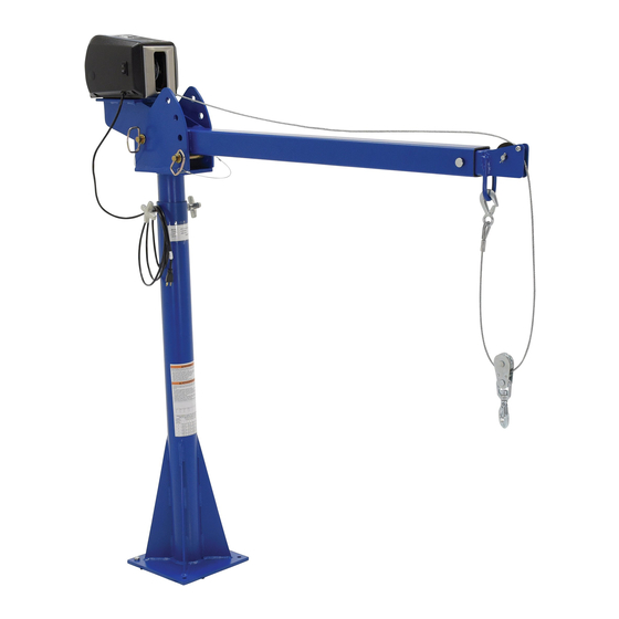
Vehicle-Mounted Jib Cranes
Contents
Installation Instructions ...................................... 2
Loading Instructions .......................................... 3
Operation Instructions ................................... 4-5
WARNING!
Material handling is dangerous. Any person who uses
or maintains this product must be familiar with the
hazards associated with it.
•
Failure to read and understand this owner's
manual before using or servicing the lifting jib
constitutes a misuse of the product.
• DO NOT leave suspended loads unattended.
Always unload the crane before leaving it.
• DO NOT use the jib to lift, support, or move people.
• Always watch the jib and the load carefully when the
jib is in use.
• Unload the jib, lower the boom and secure it to the
mast before moving the vehicle.
• DO NOT move the vehicle with a load suspended
from the jib.
• Keep clear of the boom while it is loaded or rotated.
Never allow personnel to climb under or onto any
part of a suspended load.
• Keep hands, fingers, loose clothing, etc., clear of the
winch and cable.
• Do not use the jib if any damage or unusual noise
is observed.
• AC-powered winches must only be plugged into a
115V, GFCI-protected, grounded supply circuit.
•
Confirm that all labels are in place (see "Label
placement diagram" on p. 10A-10C) and legible.
•
Apply all relevant DOT, state, and federal
regulations concerning the installation and use of
vehicle-mounted cranes.
• DO NOT modify this jib crane in any way.
Unauthorized modifications automatically void
the limited warranty and might make the crane
unsafe to use.
Revised 08-14
A company dedicated to providing ergonomic
material handling products since 1955 .
OWNER'S
MANUAL
JIB CRANES MODELS
WTJ-20, WTJ-E , & VAN-J
Exploded Parts Drawings & BOMs............... 6-8
Maintenance / Safety & Troubleshooting ........ 9
Safety Label Identification ..............................10
Warranty ........................................................ 11
REPLACEMENT PARTS
We use quality parts and materials to manu-
facture this equipment. Only install manufacturer-
approved replacment parts and accessories. VESTIL
is not responsible for problems resulting from the
use of unapproved replacement parts.
To order replacemetn parts or to ask questions
regarding the use or operation of the product,
contact VESTIL via the phone number that appears
above. Be prepared to provide the serial number,
which is displayed on the machine data label (see
label 287 on p. 10A-10C).
RECEIVING INSTRUCTIONS
Although each unit is tested and inspected prior to
shipment, it is possible that the unit was damaged
during transit. Inspect the crane closely when it
arrives. If you see evidence of damage or rough
handling to either the packaging or the product when
it is delivered, immediately make a note of it on the
Bill of Lading!
To be able to make a timely claim for freight
damage with the carrier, It is important that you
remove the packaging upon delivery. Examine the
product carefully, especially if the packaging is
damaged.
Confirm that the product matches your order.
VAN-J
WTJ-AC
E
N
G
L
I
S
H
E
S
P
A
N
O
L
F
R
A
N
Ç
A
I
S
WTJ-DC
1
Advertisement

Related Manuals for Vestil WTJ-20


Summary of Contents for Vestil WTJ-20
- Page 1 • DO NOT leave suspended loads unattended. contact VESTIL via the phone number that appears Always unload the crane before leaving it. above. Be prepared to provide the serial number, •...
- Page 2 INSTALLATION INSTRUCTIONS - WTJ, VAN-J Review this entire page before installing the jib. Consult the factory in the event there are any questions or problems at the time of installation, or for information regarding optional features not covered by the owner’s manual. Securely mount the jib on a solid surface before use! Before mounting a jib in a vehicle, consult the vehicle manufacturer for a specific mounting location and mounting hardware recommendations.If installed in a vehicle, backing or stiffener plates might be necessary to provide sufficient support for the jib.
- Page 3 LOADING INSTRUCTIONS - WTJ, WTJ-E, VAN-J All persons involved in the operation of this jib crane must understand and apply the following instructions BEFORE using it for the first time! Standard model jibs are designed for mounting on many pickup trucks and trailers. They are designed to load and unload static, non-hazardous loads from the vehicle to which the jib is mounted.
- Page 4 Secure the adjustment pin with the hitch pin. b. (WTJ-20) remove the hitch pin from the end of the angle adjustment pin; then remove the angle adjustment pin from the boom receiver bracket. Raise the boom above the d esired position and insert the angle adjustment pin through the holes in the receiver bracket.
- Page 5 Pin the free end of the lock arm to the boom stowage bracket. (WTJ-20) Remove the boom pivot pin but leave the angle adjustment pin in place. Rotate the boom until it is parallel to the mast. Secure the boom to the mast with a strap or cord to prevent it from bouncing while driving.
- Page 6 WTJ‐E‐15‐3‐DC Exploded Parts View and Bill of Materials Description Quantity Item no. Part no. 28‐514‐098 Frame, weldment, outer mast 28‐514‐097 Frame, weldment, inner mast 28‐514‐095 Weldment, outer boom 28‐514‐096 Weldment, inner boom 28‐037‐005 Lock bar 28-112-042 in. x 1 in.retaining clevis pin 28-112-029 in. x 3 in. retaining clevis pin, z-plated 28-158-003 12VDC winch 08-025-007...
- Page 7 WTJ‐E‐15‐3‐DC Capacity information and dimensions " when boom fully retracted " with boom fully extended POSITION D POSITION C POSITION B POSITION A " " " " " " with boom retracted " with boom extended " " " bolt hole in each corner 12"...
- Page 8 WTJ‐E‐15‐3‐AC Exploded Parts View and Bill of Materials Item no. Part no. Description Quantity 1 28‐514‐098 Frame, weldment, outer mast 1 2 28‐514‐097 Frame, weldment, inner mast 1 3 28‐514‐095 Weldment, outer boom 1 4 28‐514‐096 Weldment, inner boom 1 5 28‐037‐005 Lock bar 1 08-025-007 in. - 16 UNC x 1 in. threaded knob 6 2 28-158-001 120VAC winch 7 ...
- Page 9 WTJ‐E‐15‐3‐AC Capacity information and dimensions " with boom retracted " with boom fully extended POSITION D POSITION C POSITION B POSITION A " " " with boom " retracted; " " with boom fully " extended " 9 / 16 " bolt hole in 12"...
- Page 10 WTJ‐20‐3‐DC & WTJ‐20‐4‐DC Exploded Parts View and Bill of Materials Item no. Part no. Description Quantity 1 28‐514‐091 Frame, weldment, outer mast 2 28‐514‐092 Frame, weldment, inner mast Weldment, inner boom: 3 28‐514‐100 WTJ‐20‐3‐DC; or 1 28‐514‐093 WTJ‐20‐4‐DC 1 Weldment, outer boom: 4 28‐514‐099 WTJ‐20‐3‐DC; or 1 28‐514‐094 WTJ‐20‐4‐DC 1 28‐112‐042 5 in. x 1 in. clevis pin 28-158-003 6 12VDC winch 7 28‐027-004 Pulley, teardrop 33-112-034 8 in. x 3 in. clevis pin 38-112-003 ...
- Page 11 WTJ‐20‐3‐DC Capacity information and dimensions POSITION D POSITION C POSITION B POSITION A " with boom " retracted " with boom fully " extended " with boom retracted " " with boom extended " " " " bolt hole in each corner of mounting plate 10"...
- Page 12 WTJ‐20‐4‐DC Capacity information and dimensions POSITION D POSITION C POSITION B " POSITION A " with boom " retracted " with boom fully extended " " with boom retracted " with boom extended " " " 12" " bolt hole in each corner of mounting plate 10"...
- Page 13 WTJ‐20‐3‐AC & WTJ‐20‐4‐AC Exploded Parts View and Bill of Materials Item no. Part no. Description Quantity 1 28‐514‐091 Frame, weldment, outer mast 2 28‐514‐092 Frame, weldment, inner mast Weldment, inner boom: 3 28‐514‐100 WTJ‐20‐3‐AC 1 28‐514‐093 WTJ‐20‐4‐AC 1 Weldment, outer boom: 4 28‐514‐099 WTJ‐20‐3‐AC 1 28‐514‐094 WTJ‐20‐4‐AC 1 28-112-042 5 in. x 1 in. clevis pin 08-025-007 6 Pulley, teardrop 7 28‐158‐001 120VAC winch 33-112-034 8 in. x 3 in. clevis pin 08-145-037 ...
- Page 14 WTJ‐20‐3‐AC Capacity information and dimensions Position D SIDE VIEW Position C Position B Position A " with " boom retracted " with 13 / " boom extended " boom retracted " " boom extended 4 " " " 12" BOTTOM " bolt hole in each corner of VIEW mounting plate 10"...
- Page 15 WTJ‐20‐4‐AC Capacity information and dimensions Position D Position C SIDE VIEW Position B " Position A " with " boom retracted " with boom extended " " boom retracted " boom extended " " " 12" " bolt hole in each corner of BOTTOM 10"...
- Page 16 VAN‐J‐DC Exploded Parts View and Bill of Materials Item no. Part no. Description Quantity 1 28‐514‐077 Frame, inner mast weldment 2 28‐514‐187 Fame, boom subassembly 3 08‐025‐007 TT‐18‐PED, in. – 16 UNC threaded knob 4 28‐158‐003 12VDC winch 5 65076 in. x 1in. cotter pin z‐plated 6 28‐112‐042 in. x 1 in. retaining clevis pin 99-027-003 7 in. cable pulley, 3in. outer diameter, in. inner diameter 8 33006 in. USS flat washer z‐plated 9 37021 in. – 18 nylon lock nut, z‐plated #2 10 ...
- Page 17 VAN‐J‐DC Capacity information and dimensions " slot ROTATION LOCK " SCREW " " " FOLDED POSITION " " " " " " Standard specifications: Capacity = 400 pounds (181.8kg) Overall width = 12 " Usable width = 12 " Overall length = 44 "...
- Page 18 VAN‐J‐AC Exploded Parts View and Bill of Materials Item no. Part no. Description Quantity 1 28‐514‐077 Frame, inner mast weldment 2 28‐514‐225 Frame, beam subassembly 3 08‐025‐007 TT‐18‐PED, in. – 16 UNC threaded knob 4 28‐112‐042 in. x 1 in. retaining clevis pin 5 65076 in. x 1in. cotter pin z‐plated 99‐027‐003 6 in. cable pulley, 3in. outer diameter, in. inner diameter 7 28‐158‐001 120VAC winch 8 33008 in. USS flat washer z‐plated 9 33622 in. lock washer z‐plated 10 11107 in. – 16 x 1 in.
- Page 19 VAN‐J‐AC Capacity information and dimensions slot 8" ROTATION LOCK 1" SCREW 8" 15 / " FOLDED POSITION " " " " " Standard specifications: Capacity = 400 pounds (181.8kg) Overall width = 8" Usable width = 8" Overall length = 44 " Usable length = 33 "...
- Page 20 INSPECTIONS AND MAINTENANCE: Inspect and maintain the jib as described below to preserve normal operability. Remove the jib from service and DO NOT use the jib if it is damaged in any way that affects normal operation. If the unit cannot be restored to normal operating condition, discard it. The unit must be retested at 125% of its rated capacity after any repairs or modifications of either the lifting jib or its mounting WARNING! ALWAYS unload the jib before inspect i n g or work ing on it.
- Page 21 Label placement diagram: WTJ-E series jib cranes WTJ-E series cranes should be labeled as shown below. Contact Vestil to order replacement labels when necessary. 10A ...
- Page 22 Label placement diagram: WTJ-20 series jib cranes WTJ-20 series cranes should be labeled as shown below. Contact Vestil to order replacement labels when necessary. 10B ...
- Page 23 Label placement diagram: VAN-J series jib cranes VAN-J series cranes should be labeled as shown below. Contact Vestil to order replacement labels when necessary. 10C ...
- Page 24 (you) for warranty service. Who may request service? Only a warrantee may request service. You are a warrantee if you purchased the product from Vestil or from an authorized distributor AND Vestil has been fully paid.
Need help?
Do you have a question about the WTJ-20 and is the answer not in the manual?
Questions and answers