
Subscribe to Our Youtube Channel
Related Manuals for DLab DM0506


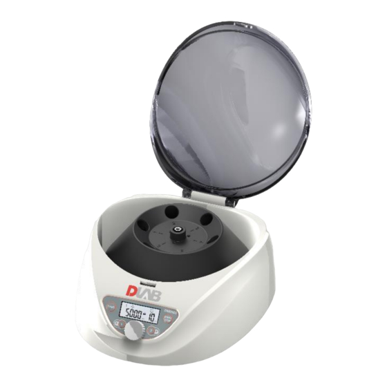
Summary of Contents for DLab DM0506
- Page 1 DM0506 Clinical Centrifuge This user manual needs to be read before operating this product. Please follow the safety instructions provided in this manual. Ver.20210717...
-
Page 2: Table Of Contents
Table of Contents Safety Warnings ..........................1 Performance indicators ....................... 3 Conformity to standards ......................3 Environmental requirements ...................... 3 3.1. Basic operating requirements ....................3 3.2. Transport and storage conditions ................... 4 Installation ........................... 4 4.1. Mounting position ........................4 4.2. - Page 3 12. RCF calculation .......................... 17 13. Warranty ........................... 18 13.1. Unit warranty ........................18 13.2. Rotor warranty ........................18 14. After-sales services ........................18...
-
Page 4: Safety Warnings
Safety Warnings The symbol is an internationally accepted safety mark. Please carefully read and fully understand the following safety rules: ⚫ Comply with the operation requirements contained herein and ensure safe operation. ⚫ Carefully read all safety information and reminders provided in this manual. ⚫... - Page 5 notify the service representative about the details. ⚫ Never touch the power cable/switch with wet hands and avoid electric shocks. ⚫ As a safety measure, ensure to maintain at least 30cm distance from the centrifuge while in operation. ⚫ For safety reasons, when the centrifuge is running, the personnel should maintain a 30cm distance from the centrifuge.
-
Page 6: Performance Indicators
1. Performance indicators 5,000rpm (300-5,000rpm) Maximum rotation speed step: 10rpm Maximum relative centrifugal 2,600×g, step: 10×g acceleration Capacity 15ml×6 Timing 30s-99 min; HOLD (continuous running) Drive motor Brushless motor Safety performance Door lock, overspeed, and onboard diagnosis system. Power Single phase, 100-240V, 50/60Hz, 2A Dimensions (mm) (Width) 300×... -
Page 7: Transport And Storage Conditions
3.2. Transport and storage conditions : -40 (1) Range of ambient temperature ℃-55℃. (2) Range of relative humidity: ≤93%.RH (3) The centrifuge must remain upright while in transit, suitably protected using wooden Kart box (4) Lift the centrifuge by the chassis only. (5) Pay attention to the centrifuge’s weight while in transit (see “1.Performance indicators”). -
Page 8: Structure
(1) This centrifuge uses two-core power cable and two-core flat plug, the latter of which may be directly connected to the power socket. (2) Ensure the rated current of the power socket is correct (>10A) and it complies to local electrical safety regulations before connecting the device to power supply. -
Page 9: Operating Panel
6. Operating panel ① ③ ④ ⑤ ② Figure 6.1 Control panel layout Legend Name Function When the rotor is fully stopped, press this key to release the door lock. When the rotor is still running, Door lock open key the door will remain locked. -
Page 10: Rotor Preparation
The main display is shown in Figure 6.2. At this time, the speed is set at 5,000rpm, indicating the set running time of 10 min. When the speed icon rotates, it indicates that the machine is in run mode. The icon rotates quicker at higher centrifuge speed. -
Page 11: Insert The Centrifuge Tubes Symmetrically Onto The Rotor In Place Without Imbalance
● Never use the rotor of other brands/ specifications on this centrifuge. ● Do not expose the rotor and its accessories to direct sunlight/Ultraviolet. 7.5. Insert the centrifuge tubes symmetrically onto the rotor in place without imbalance Caution: ⚫ Ensure to tighten the rotor to the main shaft firmly and the lid is secured properly on the rotor. - Page 12 Rotor installation and replacement 8.1.1. Locking Nut Figure 8.2 Rotor installation ◼ When placing the rotor, ensure the full contact between the rotor and the motor shaft. ◼ After placing the rotor in place, rotate the rotor gently with hands to check for normal operation of the rotor.
- Page 13 ◼ The parameter increases or decreases in a cyclic way. Turn the knob clockwise or anticlockwise to increase or decrease the adjusting parameter values. If you continue rotating the knob when the parameter hits the upper limt, it will start from the lower limit again.
-
Page 14: Rcf Operation
◼ Press the key to release the lock if the lid is still locked. ◼ The current settings will be stored. It will be loaded automatically as soon as the centrifuge is switched ON next time. (3) Retrieve the rotor and samples. 8.2. -
Page 15: Common Failures And Solutions
in this manual. ⚫ Disconnect the power supply before cleaning the centrifuge. (1) Centrifuge ◼ The color of housing might change and the label thereon might fall OFF if the centrifuge is exposed to ultraviolet for a prolonged period of time and hence cover the centrifuge with cloth to avoid exposure to light. -
Page 16: How To Open The Outer Lid
will indicate the failure code, leading to the immediate identification of possible failure causes. Phenomenon Possible cause Solution · No power supply to the power ·Eliminate failure No display after power ON socket. reconnect the power supply. · Misfitting between the rotor ·Mount the rotor properly again. -
Page 17: Introduction To Rotor And Centrifuge Tube
◼ The lever is hidden under the right bottom of the centrifuge. ◼ Pull the lever to the right and release the lock. Then open the lid. 11. Introduction to rotor and centrifuge tube Caution ●Carefully read the user manual and correctly install and use the rotor correctly. ●Don‘t exceed the maximum allowed speed of the rotor, test tube and adaptor. - Page 18 tube φ16x100mm tube 2600 2.0g/ 5000 tube Table 11.1 List of rotors and adaptors * : The tolerance is applied to tube pairs placed symmetrically in the rotor. **: The volume tolerance is a rough estimate. There is no strict match to mass tolerance. 11.1.3.
-
Page 19: Centrifuge Tube
11.2. Centrifuge tube 11.2.1. Please clean and sterilize the centrifuge tube by reference to the following table. Table 11.2 Conditions for cleaning and sterilization of centrifuge tube O: Yes X: No Condition Material Acidic cleaning agent (pH5 or lower) Acidic cleaning agent (above pH5) Alkaline cleaning agent (above Fluid cleaning pH9) - Page 20 for 20 min at 121℃(1.0 kg/cm ). Too high temperature would result in deformation of centrifuge tube. When autoclave is used, take the following steps: (1) Place the centrifuge tube upright with opening facing upward. If the centrifuge tube is placed in an inclined or horizontal manner, it will deform due to the effect of gravity.
- Page 21 13. Warranty 13.1. Unit warranty The entire unit will have one-year warranty period commencing from delivery date under the conditions of normal maintenance. 13.2. Rotor warranty The rotor will have 5-year warranty period from the date of delivery. Don’t use any rotor damaged due to corrosion or fatigue.
- Page 22 DLAB Scientific Co., Ltd.
Need help?
Do you have a question about the DM0506 and is the answer not in the manual?
Questions and answers