
Related Manuals for DLab SK-O330-Pro


Summary of Contents for DLab SK-O330-Pro
- Page 1 Shakers SK-O330-Pro LCD Digital Orbital Shaker SK-L330-Pro LCD Digital Linear Shaker VERSION20170311...
-
Page 2: Table Of Contents
CONTENTS Chapter 1: Working Principle ......................1 1.1 Introduction ........................1 1.2 Composition ........................2 Chapter 2: Removal and Installation of Instrument ............... 3 Removal ........................3 Main parts illustration ....................5 Replacement of master control board ................5 Chapter 3: Trouble shooting......................8 Chapter 4: Test Method ........................ -
Page 3: Chapter 1: Working Principle
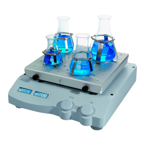
Chapter 1: Working Principle 1.1 Introduction FIG.1 Item Power Rocker Speed Time Speed Control Timer Control Function Switch Plate Display Display Knob Knob Shaker carries an object to conduct linear or circular motion at different speeds, and then mix the material. Fig. -
Page 4: Composition
Holding Bracket Upper Guard Module Base Module Motor Module Rocker Module FIG.2 FIG.3 Fig. 2 illustrates the separated structural components of SK-O330-Pro, and Fig. 3 is the Exploded View of SK-O330-Pro. Base Modules include Base, Power Board, Master Control Board, Driver... -
Page 5: Chapter 2: Removal And Installation Of Instrument
PCB etc.; Motor Modules: motor, Counterweight, Support, Eccentric Axis, Bearing, Turnplate etc.; Rocker Module: Rocker Plate, Rocker Panel, Shrapnel, Bracket etc.; Upper Guard Module: Upper Guard, LCD PCB, Knob etc. Power supply: 220/110V → power outlets → PCB → system control power supply Movement: motor drives Movement Module to rotate. - Page 6 Step 2: Remove the screws marked by red circles for retention (SK-O330-Pro). For linear shaker (SK-L330-Pro), remove the screws marked by green circles for retention; Step 3: Lift the Upper Guard from the right, and pull out 3 ribbon cables at the red ellipse icon;...
-
Page 7: Main Parts Illustration
2.2 Main parts illustration Item Spare Parts Part number Display board 18101126 Power board 18101661 motor 18100311 Drive board 18100313 Master control board 18101717 Shrapnel 2 18201095 Shrapnel 1 18201096 2.3 Replacement of master control board Step 1: As shown in the left figure, remove the 4 screws and keep them well, unplug the connector, then replace a new master control... - Page 8 2.4 Replacement of motor component Step 1: As shown in the left figure, remove the 3 screws marked by red circle, remove 3 screws in the symmetrical side and keep them well. Step 2: Remove the 4 screws marked by red circles and keep them well, take down shaker frame.
- Page 9 2.5 Replacement of photoelectronic switch Step 1: Unplug the cable marked by red circles on MS-Motro Board, as shown in figure; Step 2: When replaced photoelectronic switch, the Shaft Encoder on the motor must match with photoelectronic switch. When motor is turning, Shaft Encoder cannot be frictional contact with Photoelectronic.
-
Page 10: Chapter 3: Trouble Shooting
Chapter 3: Trouble shooting FAULT PROBLEM CAUSE SOLUTION CODE power line Check whether the power line is unplugged unplugged, an power on it again The power switch put off Put on the power switch Instruments can’t be power The fuse is broken Replace the fuse Replace power board Power board is failure... -
Page 11: Chapter 4: Test Method
Chapter 4: Test Method 4.1 The instruments does not move Step 2: Detection of moving parts Visually inspect if the steel strip of Bracket Module is broken. If no problem, remove the Bracket Module Belt and visually inspect if the belt is loose or counterweight out of position.
Need help?
Do you have a question about the SK-O330-Pro and is the answer not in the manual?
Questions and answers