Advertisement
Advertisement
Table of Contents

Related Manuals for DLab OS20-Pro


Summary of Contents for DLab OS20-Pro
- Page 1 Overhead Stirrers OS20-S/Pro OS40-S/Pro VERSION20170204...
-
Page 2: Table Of Contents
1.2 Structure..........................2 Chapter 2: Removal and Installation of Instrument ............... 3 Removal......................... 3 Main parts illustration ....................5 Circuit Connections (OS20-Pro&OS40-Pro) ..............6 Replacement of drive board..................7 Replacement of Control Modules ................. 7 Replacement of Movement ..................8 Replacement of Photosensor .................. -
Page 3: Chapter 1: Working Principle
OS40 (20)-Pro. For the control panel settings and functions of various types of Overhead Stirrers, speed RS232 control display display Interface knob Type Ⅰ √ √ OS20-Pro Type Ⅰ √ √ OS40-Pro Type Ⅱ √ OS20-S Type Ⅱ √ OS40-S... -
Page 4: Structure
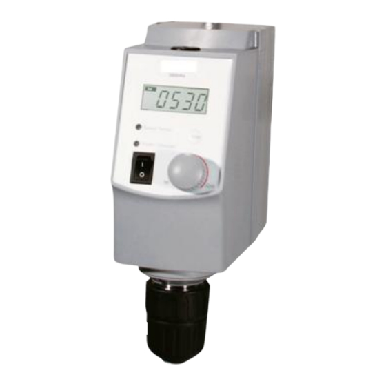
Type Ⅰ Knob: The knob of Digital Overhead Stirrer can be rotated and pressed. There is no stop point when it is rotated. The target parameters are usually set by rotating, and the function is started by pressing; Type Ⅱ Knob: The knob of Standard Overhead Stirrer can be rotated. There is a stop point when being rotated and only can be rotated more than half a circle. -
Page 5: Chapter 2: Removal And Installation Of Instrument
1 Front Guard 2 Rubber Cap 3 Nail 4 Membrane 5 Knob 6 Power Switch 7 Knob Lock 8 Knob Switch 9 Master Control Board 10 Coded Disc 11 Rubber Ring 12 Shaft 13 Photoelectric switch 14 M3*10 Socket Hexagon Screw 15 Bearing 16 Belt 17 Spindle Pulley 18 Bearing... - Page 6 Step 1: Turn over the instrument, remove the four screws marked red circles and keep them to be properly preserved. Remove the screws marked green circles at the back of the instrument and keep them to be properly preserved. Step 2: Separate the front and rear guard, and respectively pull out cables marked by red circle.
-
Page 7: Main Parts Illustration
Step 4: Separate the guard module and movement module. 2.2 Main parts illustration Item Spare part 0S20-Pro OS20-S OS40-Pro OS40-S Master Control Board 18100472 18101620 18100472 18101620 Encoder/potentiometer 18100483 18100489 18100483 18100489 Driven Board 18100651 18101619 18100473 18101619 Motor 18100493 18100493 18100492 18100492... -
Page 8: Circuit Connections (Os20-Pro&Os40-Pro)
2.3 Circuit Connections (OS20-Pro&OS40-Pro) Step 1: Circuit connections are performed at the red circle. Before close the upper guard and install instrument, please carefully check the cables and make sure they are correctly connected. Power Interface Power switch Interface Ribbon Cable Interface of LCD PCB... -
Page 9: Replacement Of Drive Board
2.4 Replacement of drive board Step 1: Pull out the cables of Driven Board. Remove the screws and ceramic gaskets (marked in red circles) of fixing Driven Board by tools and keep them to be properly preserved; Step 2: Turn over the old Driven Board to be removed, and remove thermal silicagel pads on the Driven Board, to affix it to the corresponding position on the new PCB... -
Page 10: Replacement Of Movement
2.6 Replacement of Movement Step 1: Remove cables movement module and guard module.Remove the screws of movement module and guard module at the bottom of the instrument retention. Re-assemble the instrument after new movement module is replaced. 2.7 Replacement of Photosensor Step 1: Remove the screws (marked red circles) by tools and keep... -
Page 11: Chapter 3: Trouble Shooting
Chapter 3: trouble shooting FAULT CODE PROBLEM CAUSE SOLUTION Check and connect the power No power supply supply, then power on again No operation response The power switch put off Put on the power switch (LED off) As shown in the chapter 2.1 Some cable Connection is open the instrument and check failure... - Page 12 shaft; if not, you should fix them with adhesive at the place where parts contact each other. Check whether the photosensor PCB is disordering. If it is, please replace the photosensor. Check relative position photosensor and coded disc. Coded disc should lie in the middle of photosensor notch, and coded disc cannot be contact with photosensor...
Need help?
Do you have a question about the OS20-Pro and is the answer not in the manual?
Questions and answers