Advertisement
Quick Links
USER GUIDE | UG:014
®
VI Chip
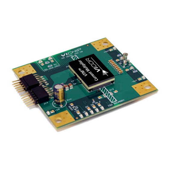
VTM™ Evaluation Board
Contents
Page
Introduction
Features
Board Description
General Components
Test Points and
Sockets Description
Schematic
Assembly Drawings
Bill of Materials
PRM™ & VTM™
10
10
10
11
Push-Pin
11
11
11
Introduction
1
This evaluation board offers a convenient means to evaluate the performance of the Vicor VTM current
2
multiplier. All evaluation boards include sockets for easy plug-and-play insertion and removal of
through-hole components and wires. The board provides lugs for power connections, connectors for
3
easy PRM-VTM evaluation board interconnects and Kelvin voltage-measurement test points of all pins of
the VTM. Please refer to the appropriate VTM data sheet for performance and operating limits, available
4
for downloading at www.vicorpower.com.
5
6
8
9
IMPORTANT NOTICE:
Please read this document before setting up a VTM evaluation board.
This user guide is not comprehensive and the operator should not substitute it for common sense and
good practice. The following procedures should be followed during operation:
Wear approved safety glasses when testing electronic product.
n
n
n
n
Provide strain relief for wires and secure the board on the test bench to avoid displacement.
n
n
Remove the power and use caution when connecting and disconnecting all test probes and interface
lines to avoid unintentional short circuits and contact with hot surfaces.
n
n
Never attempt to disconnect the evaluation board from a PRM™ evaluation board while power is
applied. This system is not designed to demonstrate the hot-plug capability.
UG:014
Page 1
Advertisement

Related Manuals for VICOR VI Chip VTM


Summary of Contents for VICOR VI Chip VTM
-
Page 1: Table Of Contents
Contents Page Introduction This evaluation board offers a convenient means to evaluate the performance of the Vicor VTM current Features multiplier. All evaluation boards include sockets for easy plug-and-play insertion and removal of through-hole components and wires. The board provides lugs for power connections, connectors for... - Page 2 Contents All VTM™ evaluation boards arrive with the following contents. (The user guide can be downloaded from www.vicorpower.com.) 1 x VTM Evaluation board ® 1 x VI Chip push-pin heat sink 2 x VI Chip push pins for heat-sink installation 1 x Hardware kit 2 x Through-hole mating connectors 1 x Through-hole 22µF input capacitor...
- Page 3 Board Description The following section provides a detailed description of the evaluation board components, test points and sockets. Figure 1 Board description Figure 2 Power/signal connectors pinout (front view) VTM_–IN +OUT +OUT –OUT –OUT –S V_TM +OUT +OUT –OUT V_IM V_PC –OUT Signal Connector...
- Page 4 General Components VTM™ (PS10). Input lugs (+IN and –IN): Sized for #10 hardware. Use these for making connection to the input source. This board does not contain reverse-polarity protection. Check for proper polarity before applying power. Input filtering: Input capacitor (CIN) and filtering (ceramic capacitors) allows for stable operation with most input sources.
- Page 5 Test Points and Sockets Description Each test-point socket accepts 0.015 – 0.025 inch diameter leads of solid wires and through-hole components for use with external circuitry and test equipment. All test points are aligned on the board’s edge for easy access, measurement and external circuitry connections. Each point is labeled and is accompanied by an additional adjacent socket.
- Page 6 Schematic Figure 3a Full-chip VTM™ evaluation board UG:014 Page 6...
- Page 7 Schematic (Cont.) Figure 3b Half-chip VTM™ evaluation board UG:014 Page 7...
- Page 8 Assembly Drawings Figure 4a Top view: full-chip VTM™ evaluation board TP18 TP19 FID02 HS10 TP15 PS10 TP14 PF15 FID01 Figure 4b Top view: half-chip VTM evaluation board TP18 TP19 FID02 HS10 TP15 PS10 TP14 PF15 PF18 FID01 UG:014 Page 8...
- Page 9 Murata K = 1, 2/3, CAP X7R 1.0µF C12 – C19 GRM31CR72A105KA01L 10% 100V 1206 Manufacturing 1/2, VTMs Full-chip SNGLTD PCB FULL Vicor 39261 CHIP VTM CB VTM boards Half-chip SNGLTD PCB HALF Vicor 39262 CHIP VTM CB VTM boards...
-
Page 10: Evaluation Boards
PRM™ & VTM™ Evaluation Boards The VTM evaluation board has been designed for compatibility with all PRM evaluation boards to accommodate any PRM-VTM combination. The VTM evaluation board contains dual connectors designed to mate with J10 and J13 on PRM board. An additional signal connector shares VTM signal pins along with TM, S+ and S–... -
Page 11: Paralleling
VTM. It may be necessary to install an input capacitor across the secondary terminals to decouple the input source. Part Ordering Information The VTM evaluation boards can be ordered from the Vicor website. To order the demo boards, substitute VTM with VTD in VTM part number. http://www.vicorpower.com/dc-dc-converters-board-mount/vtm for part number listing. - Page 12 ANY AND ALL LIABILITY FOR INCLUSION AND/OR USE OF VICOR PRODUCTS IN SUCH EQUIPMENT OR APPLICATIONS AND THEREFORE SUCH INCLUSION AND/OR USE IS AT YOUR OWN RISK. Terms of Sale The purchase and sale of Vicor products is subject to the Vicor Corporation Terms and Conditions of Sale which are available at: (http://www.vicorpower.com/termsconditionswarranty) Export Control This document as well as the item(s) described herein may be subject to export control regulations.
Need help?
Do you have a question about the VI Chip VTM and is the answer not in the manual?
Questions and answers