Table of Contents
Advertisement
Quick Links
USER GUIDE | UG:017
Analog Control DCM3623 and DCM4623 ChiP™
Evaluation Board
Arthur Russell
®
VI Chip
Applications Engineering
October 2014
Contents
Introduction
Contents
Features
Board Description
General Components
Test Points Description
Schematic, Assembly Drawing
and Bill of Materials
Recommended Test
Equipment
Basic Connections
Board Operation Details
Trim Control
Fault Monitoring
Chassis Ground
Paralleling
Arrow.com.
Downloaded from
Introduction
Page
1
The Analog Control DCM3623 and DCM4623 ChiP evaluation boards described in this document are
designed to be used with the DCM family of isolated, DC-DC converters. The DCM3623 board is used
3
for the analog control, low input voltage DCM3623 ChiP products, while the DCM4623 board is used
3
for the analog control, high input voltage (offline) DCM4623 ChiP products.
4
The DCM evaluation board can be configured for various enabling and fault monitoring schemes,
as well as to exercise various modes of trimming, depending on the application requirements. The
4
evaluation board can be used to evaluate DCMs in either a stand-alone configuration, or as an
6
array of modules.
7
Enable options:
1.
Onboard mechanical switch (default)
14
2.
External control
14
14
Trim options:
15
1.
Fixed trim operation (default): the TR pin is permitted to float at initial start up.
15
The DCM disables output trimming and the output trim is programmed to the nominal rated V
16
2.
Variable trim operation, onboard variable resistor: The trim pin voltage is ratiometric,
with a rheostat working against a pull-up resistor inside the DCM to VCC.
16
3.
Variable trim operation, off-board control: The trim pin voltage is controlled via external
programming control, which is referenced to the –IN of each specific DCM in the system.
Fault monitor options:
1.
Onboard LED: the FT pin drives a visible LED for visual feedback on fault status.
2.
Onboard optocoupler: the FT pin drives an onboard optocoupler to bring
fault status across the primary-secondary isolation boundary.
UG:017
.
OUT
Page 1
Advertisement
Table of Contents

Subscribe to Our Youtube Channel
Related Manuals for VICOR ChiP DCM3623


Summary of Contents for VICOR ChiP DCM3623
- Page 1 USER GUIDE | UG:017 Analog Control DCM3623 and DCM4623 ChiP™ Evaluation Board Arthur Russell ® VI Chip Applications Engineering October 2014 Introduction Contents Page Introduction The Analog Control DCM3623 and DCM4623 ChiP evaluation boards described in this document are designed to be used with the DCM family of isolated, DC-DC converters. The DCM3623 board is used Contents for the analog control, low input voltage DCM3623 ChiP products, while the DCM4623 board is used Features...
- Page 2 IMPORTANT NOTICE: Hazardous voltages are present on the DCM Evaluation Board under power. PERSONAL CONTACT WITH LINE VOLTAGE MAY RESULT IN SEVERE INJURY, DISABILITY, OR DEATH. IMPROPER OR UNSAFE HANDLING OF THIS BOARD MAY RESULT IN SERIOUS INJURY OR DEATH. Read the precautions below entirely BEFORE using the DCM Evaluation Board.
- Page 3 These boards provide a convenient way to evaluate/demonstrate the performance of Vicor DCM products. Kelvin connections are provided for accurate voltage measurements on power nodes. Sockets are provided to permit quick installation and changing of bulk filtering capacitors. The evaluation board also provides lugs for input/output connections, test points and sockets for easy connection to standard test-equipment, and a high performance air cooled heat sink assembly.
-
Page 4: Board Description
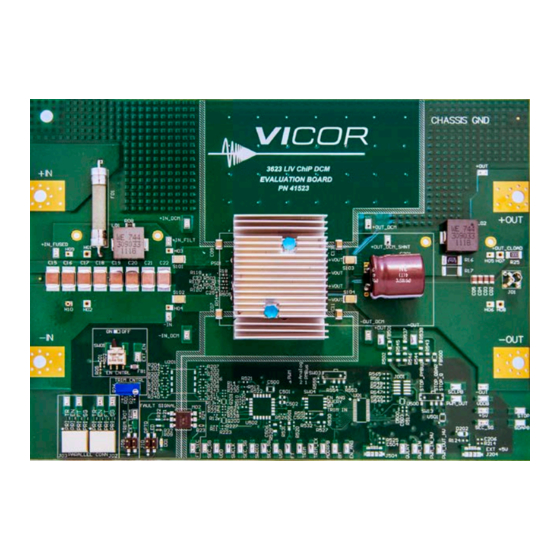
Board Description The following section provides a detailed description of the evaluation board components, test points and sockets. General Components DCM (PS01) Input lugs: Sized for #10 hardware. Use these for making connection to the input source. This board does not contain reverse polarity protection. Check for proper polarity before applying the power. - Page 5 Figure 1 DCM3623 evaluation board photo, top side Figure 2 DCM4623 evaluation board photo, top side UG:017 Page 5 Arrow.com. Arrow.com. Arrow.com. Arrow.com. Arrow.com. Downloaded from Downloaded from Downloaded from Downloaded from Downloaded from...
-
Page 6: Test Points Description
Test Points Description Test nodes are labeled and include a SMT test point for attaching miniature probes, clips or hooks. Table 1 Primary-referred Name Description test point descriptions +IN_FUSED, Provide measurement test points for the input voltage to the board in various locations, +IN_FILT, relative to the –IN board lug. -
Page 7: Schematic, Assembly Drawing And Bill Of Materials
Schematic, Assembly Drawing and Bill of Materials Figure 3 DCM3623 evaluation board schematic UG:017 Page 7 Arrow.com. Arrow.com. Arrow.com. Arrow.com. Arrow.com. Arrow.com. Arrow.com. Downloaded from Downloaded from Downloaded from Downloaded from Downloaded from Downloaded from Downloaded from... - Page 8 Schematic, Assembly Drawing and Bill of Materials (Cont.) Figure 4 DCM4623 evaluation board schematic UG:017 Page 8 Arrow.com. Arrow.com. Arrow.com. Arrow.com. Arrow.com. Arrow.com. Arrow.com. Arrow.com. Downloaded from Downloaded from Downloaded from Downloaded from Downloaded from Downloaded from Downloaded from Downloaded from...
- Page 9 Schematic, Assembly Drawing and Bill of Materials (Cont.) Figure 5 DCM3623 evaluation board, J108 assembly drawing, top side J104 J106 S101 PS01 S103 R118 R503 C201 R119 R504 R120 R505 S104 S102 HS02 HS01 J105 J107 R204 R207 L202 SW01 L203 R565 R202...
- Page 10 CNY17-3X017T R02, R04, R05, RES 0 OHM JUMPER 0603 RK73Z1JTTD R18, R19, R20 PS01 Design specific - See table 5 BOMs VICOR RES 1Ω ¼W 5% 1206 RK73B2BTTE1R0J RES 250mΩ 1W 2512 VISHAY WSL2512R2500FEA R09, R21 RES 1kΩ 1/10W 5% 0603...
- Page 11 C15 – C22 CAP X7R 4.7µF 20% 100V 2220 C5750X7R2A475M230KA IND 0.33µH 20% 50A WURTH 744309033 HS01 - HS02 DCM3623 DUAL HTSNK VICOR 40526 EXCELTOOL S101 RES 0Ω JUMPER 1612 COPPER 29581 and DIE CAP ALEL 680µF 20% 63V RADIAL...
- Page 12 Example: BOM additions, Description Manufacturer Designator Part Number components which are Evaluation board number: DCM3623E50M06A8M00 DCM model specific. PS01 DCM3623 VICOR DCM3623T50M06A8M00 FUSE 30A 125V AXIAL LITTELFUSE 324 030P CAP ALEL 10000µF 20% 10V RADIAL C201 NICHICON URS1A103MHD1TN 18 x 26.5...
- Page 13 18 x 16.5 General BOM rules for various DCM Evaluation Boards PS01: This is the Vicor DCM, whose part number is coded in the evaluation board part number. For example, eval board DCM4623ED2K53E0M00 uses DCM4623TD2K53E0M00. F01: This is the input fuse. See the data sheet for the specific DCM for appropriate fuse needed to meet listed safety agency approvals.
-
Page 14: Recommended Test Equipment
Recommended Test Equipment The following is a list of recommended test equipment. Safety glasses DC power supply: Refer to the specific DCM model data sheet to ensure the supply has sufficient power and current capability, especially at low line, to satisfy current inrush when the DCM is started Electronic load: Refer to the specific DCM model data sheet to ensure the load has sufficient power handling and current capability for testing... -
Page 15: Trim Control
Trim Control Jumper block J09 configures trimming. With no jumpers installed, neither the trim potentiometer nor the test point for external trim control is connected to the TR net. Note that the paralleling connectors always connect to the TR net. With a jumper loaded across J09.1 and J09.2, the trim potentiometer R26 is connected as a rheostat between the TR node and SG. -
Page 16: Chassis Ground
Both the visible LED and the opco-coupler draw current from the FT node in a fault condition. The FT pin on the DCM has limited drive-high capabilities, and so care must be taken to avoid excess loading of the pin. To avoid overload, do not configure J10 to use both the LED and opto-coupler indicators simultaneously. - Page 17 The –IN lugs must be connected together if the paralleling connector is used, or if the EN, TR, or FT pins are interconnected in any fashion. However if all control signals of all DCMs are fully isolated from one another, then both the +IN and –IN lugs can remain independent across the evaluation boards, and the DCMs can be operated with fully independent input supplies.
-
Page 18: Export Control
Customer Service: apps@vicorpower.com Technical Support: ©2017 – 2022 Vicor Corporation. All rights reserved. The Vicor name is a registered trademark of Vicor Corporation. All other trademarks, product names, logos and brands are property of their respective owners. 10/22 Rev 1.7 Page 18 Arrow.com.
Need help?
Do you have a question about the ChiP DCM3623 and is the answer not in the manual?
Questions and answers