Table of Contents
Advertisement
Quick Links
USER GUIDE | UG:702
NBM2317 Bus Converter
SM-ChiP™ Evaluation Board
Contents
Page
10
10
11
1
2
2
3
3
4
9
Introduction
The NBM2317 bus converter evaluation board described in this document is designed to be used with
the NBM2317S60D1580T0R, SM-ChiP non-isolated, fixed-ratio, bidirectional DC-DC bus converters.
Note: Refer to
UG:701
for NBM2317S60E1560T0R evaluation board user guide.
The focus of this document is to assist the user in evaluating of the NBM2317 SM-ChiP™ family.
The NBM™ evaluation board can be configured for various enabling and fault monitoring schemes, as
well as to exercise various loading conditions depending on the application requirements. The evaluation
board can be used to evaluate NBMs in stand-alone configuration.
It is important to remember that the fast response of NBMs can readily show the limitations of the
source, load and associated wiring connected to the evaluation board. Care should be taken to minimize
the source impedance as well as high- and low-voltage side interconnect impedances in order to fully
realize the NBM performance.
The NBM non-isolated topology allows start up in step-down and step-up directions and provides
bidirectional protections. However, if the powertrain is disabled by any fault protection and low
side voltage V
is present, a voltage V
LO
high-voltage side.
equal to V
minus three diode drops will appear on the
HI
LO
UG:702
Page 1
Advertisement
Table of Contents

Related Manuals for VICOR NBM2317S60D1580T0R


Summary of Contents for VICOR NBM2317S60D1580T0R
-
Page 1: Table Of Contents
Operation Heat Sink Installation Introduction The NBM2317 bus converter evaluation board described in this document is designed to be used with the NBM2317S60D1580T0R, SM-ChiP non-isolated, fixed-ratio, bidirectional DC-DC bus converters. Note: Refer to UG:701 for NBM2317S60E1560T0R evaluation board user guide. -
Page 2: Important Notice
Basic input and output filtering - using low ESR ceramic capacitors Test points for NBM signal terminals (TM/OG and EN) Kelvin voltage test points for all power terminals for input and output voltage measurements Table 1 Part Number Description Evaluation baords NBM2317S60D1580T0R evaluation board NBM2317E60D1580T0R UG:702 Page 2... -
Page 3: Board Description
Board Description This board provides a convenient way to evaluate or demonstrate the performance of the Vicor NBM2317 SM-ChiP™ products. Kelvin connections are provided for accurate voltage measurements on power nodes and signals. The evaluation board also provides lugs for input / output connections and test points for easy connection to standard test equipment. -
Page 4: Test Point Description
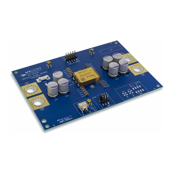
Heat sink mounting: J502 and J503 are the heat sink mounting holes with pre-installed surface-mount nuts. Use these holes for mounting the heat sink assembly provided in the evaluation board box. The heat sink kit is Vicor part number MB-EVAL-NBM2317-1X, see Heat Sink Installation section. - Page 5 Figure 2a PCB#51018 evaluation board photo, top side Figure 2b PCB#51018 evaluation board photo, bottom side UG:702 Page 5...
- Page 6 Figure 3a PCB#51018 evaluation board schematic UG:702 Page 6...
-
Page 7: Enable Control
Figure 3b PCB#51018 evaluation NBM TEST POINTS board schematic, cont. J400 J401 J402 VSS_S_HI VHI_S VSS_S_HI VHI_S NBM_VHI 48547 48547 VSS_S_LO VLO_S VSS_S_LO VLO_S CN10_DIGIKEY_95278 42829 J403 EN_CTRL TM/OG TM/OG Header 3X2 C400 C401 0.1uF 0.1uF DESIGN NOTE: Placeholder Only 0603 0603 Optional decoupling caps... - Page 8 Figure 4a PCB#51018 evaluation board assembly drawing, top side FID03 MTG04 MTG03 LABEL J402 J400 J401 C205 C218 F200_A C206 C212 F200_B C207 C213 C208 J502 C211 C209 C210 J500 J501 C303 C302 C307 C304 PS200 C400 C301 C300 C306 C305 J504 J505...
-
Page 9: Bill Of Materials
Panasonic 80SXV56M C302 C303 Not Applied C304, C305, CAP ALEL POLY 680µF 20% 20V 10x12.7 Panasonic 20SVPK680M C306, C307 F200_A Fuse 30A 125VAC FAST 12.5x4.5 SMD Littelfuse 0456030.ER High-side input fuse PS200 Bidirectional NBM2317 SM-ChiP Vicor NBM2317S60D1580T0R UG:702 Page 9... -
Page 10: Recommended Test Equipment
Recommended Test Equipment The following is a list of recommended test equipment: Safety glasses DC power supply: Refer to the specific NBM™ model data sheet to ensure the supply has sufficient power and current capability. Electronic load: Refer to the specific NBM model data sheet to ensure the load has sufficient power handling and current capability for testing Cooling fan Digital multi-meters (DMMs) -
Page 11: Heat Sink Installation
NBM2317 assembly onto an evaluation board or a customer application board. The evaluation board comes with heat sink mounting holes and pre-installed PEM nuts, which makes the heat sink installation easy. Utilize the hardware components provided in the heat sink assembly kit, Vicor part number MB- EVAL-NBM2317-1X. Table 4... - Page 12 Fasten one screw at a time up to two turns to apply equal pressure on the surface of the SM-ChiP, alternating sides and up to the maximum of 8 – 11 turns. Springs provide 10 – 12.8psi for 8 – 11 turns, respectively. Figure 6 Vicor p/n MB-EVAL-NBM2317- 1X exploded view Step 3 Step 4...
-
Page 13: Terms Of Sale
Customer Service: Technical Support: apps@vicorpower.com ©2021 – 2024 Vicor Corporation. All rights reserved. The Vicor name is a registered trademark of Vicor Corporation. All other trademarks, product names, logos and brands are property of their respective owners. 08/24 Rev 1.3...
Need help?
Do you have a question about the NBM2317S60D1580T0R and is the answer not in the manual?
Questions and answers