Table of Contents
Advertisement
Quick Links
USER GUIDE | UG:020
Analog Control DCM2322 ChiP™
Evaluation Board
VamshiKrishna Domudala
Applications Engineering
Contents
Page
10
10
10
11
12
13
Introduction
1
The Analog Control DCM2322 ChiP evaluation board described in this document is designed to be used
3
with the DCM family of isolated, DC-DC converters. The DCM2322 board is used for the analog control,
low input voltage DCM2322 ChiP products.
3
The DCM evaluation board can be configured for various enabling and fault-monitoring schemes,
4
as well as to exercise various modes of trimming, depending on the application requirements. The
evaluation board can be used to evaluate DCMs in either a standalone configuration or as an
4
array of modules.
5
6
Operation Mode Options
7
Operation mode of the DCM can be selected based on the voltage seen by the DCM at its EN pin at first
8
start up following application of V
1.
Array mode (default): the EN pin is permitted to float at initial start up.
The DCM enables the output and latches in array mode of operation.
2.
Enhanced V
Regulation mode: applying a specified voltage level on the EN pin during initial
OUT
start up will latch the DCM in enhanced V
Enable options:
1.
On-board mechanical switch (default)
2.
External control
Trim options:
1.
Fixed trim operation (default): the TR pin is permitted to float at initial start up.
The DCM disables output trimming and the output trim is programmed to the nominal rated V
2.
Variable trim operation, on-board variable resistor: The trim pin voltage is ratiometric,
with a rheostat working against a pull-up resistor inside the DCM to V
3.
Variable trim operation, off-board control: The trim pin voltage is controlled via external
programming control, which is referenced to the -IN of each specific DCM in the system.
Fault monitor options:
1.
On-board LED: the FT pin drives a visible LED for visual feedback on fault status.
2.
On-board optocoupler: the FT pin drives an on-board optocoupler to bring
fault status across the primary-secondary isolation boundary.
. Two operation modes that can be selected are:
IN
regulation mode.
OUT
INFORMATION SUBJECT TO CHANGE WITHOUT NOTICE
UG:020
.
OUT
.
CC
Page 1
Advertisement
Table of Contents

Subscribe to Our Youtube Channel
Related Manuals for VICOR DCM2322


Summary of Contents for VICOR DCM2322
-
Page 1: Table Of Contents
The Analog Control DCM2322 ChiP evaluation board described in this document is designed to be used Contents with the DCM family of isolated, DC-DC converters. The DCM2322 board is used for the analog control, low input voltage DCM2322 ChiP products. - Page 2 IMPORTANT NOTICE: Hazardous voltages are present on the DCM Evaluation Board under power. PERSONAL CONTACT WITH LINE VOLTAGE MAY RESULT IN SEVERE INJURY, DISABILITY, OR DEATH. IMPROPER OR UNSAFE HANDLING OF THIS BOARD MAY RESULT IN SERIOUS INJURY OR DEATH. Read the precautions below entirely BEFORE using the DCM Evaluation Board.
-
Page 3: Contents
This board provides a convenient way to evaluate/demonstrate the performance of Vicor DCM products. Kelvin connections are provided for accurate voltage measurements on power nodes. Sockets are provided to permit quick installation and changing of bulk filtering capacitors. The evaluation board also provides lugs for input/output connections, test points and sockets for easy connection to standard test equipment, and a high-performance air-cooled heat sink assembly. -
Page 4: Board Description
Board Description The following section provides a detailed description of the evaluation board components, test points and sockets. General Components DCM (PS01). Input lugs: Sized for #10 hardware. Use these for making connection to the input source. This board does not contain reverse polarity protection. Check for proper polarity before applying the power. -
Page 5: Test Points Description
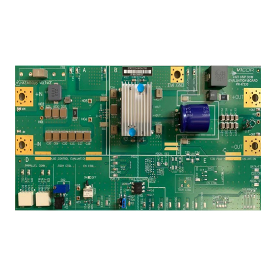
Figure 1 DCM2322 evaluation board photo, top side Test Points Description Test nodes are labeled and include a SMT test point for attaching miniature probes, clips or hooks. Table 1 Name Description Primary referred +IN_FUSED, Provide measurement test points for the input voltage to the board in various locations, rela-... -
Page 6: Schematic
Schematic Figure 2 DCM2322 evaluation board schematic UG:020 Page 6... -
Page 7: Assembly Drawing
Assembly Drawing Figure 3 DCM2322 evaluation board, assembly drawing, top side UG:020 Page 7... -
Page 8: Bill Of Materials
Bill of Materials Table 3 Reference Manufacturer DCM evaluation board BOM Description Manufacturer Designator Part Number Common Components C01, C02, C03, C05, C06, C07, CAP X7T 2.2µF 20% 250V 2220 C5750X7T2E225M250KA C08, C09, C10, CAP X7R 0.10µF 10% 16V 0603 0603YC104KAT2A CAP X7R 0.001µF 10% 50V 0603 C1608X7R1H102K080AE... - Page 9 DCM2322TA5N13A2T60 General BOM rules for various DCM Evaluation Boards PS01: This is the Vicor DCM, whose part number is coded in the evaluation board part number. For example, evaluation board DCM2322EA5N13A2T60 uses DCM2322TA5N13A2T60. F01: This is the input fuse. See the data sheet for the specific DCM for appropriate fuse needed to meet listed safety agency approvals.
-
Page 10: Recommended Test Equipment
Recommended Test Equipment The following is a list of recommended test equipment. Safety glasses DC power supply: Refer to the specific DCM model data sheet to ensure the supply has sufficient power and current capability, especially at low line, to satisfy current inrush when the DCM is started Electronic load: Refer to the specific DCM model data sheet to ensure the load has sufficient power handling and current capability for testing... -
Page 11: Enable)
EN (Enable) The EN pin provides two functionalities: Enables and disables the DCM converter. Selects Array mode or Enhanced V Regulation mode. The EN pin is referenced to the –IN pin of the converter. It has an internal pull up to V through a 10kΩ... -
Page 12: Trim Control
Trim Control Jumper block J03 configures trimming. With no jumpers installed, neither the trim potentiometer nor the test point for external trim control is connected to the TR net. Note that the paralleling connectors always connect to the TR net. With a jumper loaded across J03.1 and J03.2, the trim potentiometer R02 is connected as a rheostat between the TR node and PRI_SG. -
Page 13: Chassis Ground / Emi_Gnd
Chassis Ground / EMI_GND The heat sink assembly of the DCM is connected to the EMI_GND node of the board, as well as the y-caps from each power connection of the DCM. A connection from the EMI_GND lug to earth ground is required. - Page 14 ANY AND ALL LIABILITY FOR INCLUSION AND/OR USE OF VICOR PRODUCTS IN SUCH EQUIPMENT OR APPLICATIONS AND THEREFORE SUCH INCLUSION AND/OR USE IS AT YOUR OWN RISK. Terms of Sale The purchase and sale of Vicor products is subject to the Vicor Corporation Terms and Conditions of Sale which are available at: (http://www.vicorpower.com/termsconditionswarranty) Export Control This document as well as the item(s) described herein may be subject to export control regulations.
Need help?
Do you have a question about the DCM2322 and is the answer not in the manual?
Questions and answers