Table of Contents
Advertisement
Quick Links
USER GUIDE | UG:305
PI3741-0x-EVAL1
®
Cool-Power
ZVS Switching Regulators Buck-Boost Evaluation Board
Contents
Page
Introduction
Bill of Materials
Typical Connections
Vicor PCB Edge
Connector Description
PAD Numbering
PAD Definitions
PCB Design Files
1
2
4
5
5
6
7
Introduction
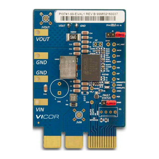
The PI3741‑0x‑EVAL1 evaluation board demonstrates the features and benefits of the Vicor ZVS
Buck‑Boost regulator; pre‑configured for either a 24 or 48V output voltage and rated for up to
150W. Please refer to the corresponding PI3741‑0x‑LGIZ data sheet for all power specifications. The
PI3741‑0x‑EVAL1 evaluation board is used with the following ZVS buck‑boost products:
PI3741‑00‑LGIZ, PI3741‑01‑LGIZ.
The evaluation board provides several options for applying input power (VIN and GND) and output load
(VOUT and GND). The user can solder tab‑style banana jacks or wire, use threaded connectors with
retaining nuts or solder turret pins for clip‑on connections.
The evaluation board comes with all of the PI3741‑0x‑LGIZ's features accessible to the user. The
current‑monitor function (IMON) is set up to monitor the PI3741‑0x‑LGIZ's output current, sensed across
a 5mΩ resistor. The general purpose amplifier (VDIFF) comes pre‑set with a gain of 2, but can be easily
reconfigured for differential measurements by adding extra 0603 resistors.
The I/O pins are brought out to the right edge of the evaluation board to allow for easy monitoring
or for adding additional circuitry. The status of the PGD pin is indicated by a dual‑colored LED; red
indicating a fault and green indicating no faults. The SYNCO (sync out) and SYNCI (sync in) pins are
accessible to allow for paralleling or for synchronizing to an external clock. Shorting J5 between IMON
and VSP on the board will connect the output of IMON to the positive input of the general purpose
amplifier, allowing for user‑designed signal scaling and conditioning.
A footprint for an external Soft‑Start capacitor (0603) is available to tailor the start‑up profile of the
converter. The error amplifier's output (EAO) is brought to a pin and in conjunction with the soft‑start
pin can be used for paralleling converters. The error amplifier's input (EAIN) is not directly connected to
a pin, but connects to the pin EXT_VREF via a 10kΩ series resistor. Applying a DC voltage to this pin will
allow the user to change the regulated output voltage without changing the feedback network.
The board is designed with an edge connector to facilitate testing at the factory, but this connection
can also be used for board evaluation. The PCB is 4‑layer FR‑4 170Tg material with 2oz copper per layer,
ENIG pad finish and a board thickness of 0.062in.
UG:305
Page 1
Advertisement
Table of Contents

Related Manuals for VICOR PI3741-0x-EVAL1


Summary of Contents for VICOR PI3741-0x-EVAL1
- Page 1 PCB Design Files Introduction The PI3741‑0x‑EVAL1 evaluation board demonstrates the features and benefits of the Vicor ZVS Buck‑Boost regulator; pre‑configured for either a 24 or 48V output voltage and rated for up to 150W. Please refer to the corresponding PI3741‑0x‑LGIZ data sheet for all power specifications. The PI3741‑0x‑EVAL1 evaluation board is used with the following ZVS buck‑boost products:...
-
Page 2: Bill Of Materials
TSW‑148‑07‑F‑S FP0404 Series 65nH Cooper FP0404R1‑R065‑R Inductor LMAG 0.9µH HCV1206 Inductor Cooper HCV1206‑R90‑R PI37xx‑xx Edge Connector VICOR PCB0175rD Eval Board Low Voltage ZVS PI3741 ZVS Buck‑Boost VICOR PI3741‑0x‑LGIZ B‑B SIP 10 x 14mm Resistor, 1%, 1.00kΩ Rohm MCR03EZPFX1001 0.1W, 0603... - Page 3 Figure 1 Evaluation board schematic COMP UG:305 Page 3...
-
Page 4: Typical Connections
Figure 2 Evaluation board details Typical Connections Figure 4 illustrates the typical input supply and output load connections required to power the PI3741‑x0 evaluation board. The test points on the right side of the board provide access to key nodes used to assess the board's performance. -
Page 5: Connector Description
Vicor PCB Edge Connector Description SAMTEC Reference Mechanical Drawings: based on EXTreme LPHPower™ Socket Assembly series, available from Samtec’s website PCB Dimensions: Recommended PCB layout for LPHS‑XX‑XX‑X‑VXX‑XX PCB Layout.pdf Right‑angle Socket: LPHS‑XX‑XX‑X‑RTX‑XX‑MKT.pdf Vertical Socket: LPHS‑XX‑XX‑X‑VXX‑XX‑MKT.pdf Figure 4 Edge connector details... -
Page 6: Pad Definitions
Schematic Symbol Figure 7 Schematic of edge connector PAD Definitions Table 3 Name Descirption PAD Definitions P1,P2 PGND Power ground connection for the input supply and output load VOUT Output voltage connection Input voltage connection 1, 2, 6, 7, 8, 10 SGND Signal ground used as reference for I/O measurements 11, 12... -
Page 7: Pcb Design Files
PCB Design Files website ODB++ evaluation board design files are available for download on the Vicor Table 4 Deisgn Product Link to Download Design files File Format PI3741‑0x‑EVAL1 ODB++ PI3741‑0x Eval ODB++.zip UG:305 Page 7... - Page 8 ANY AND ALL LIABILITY FOR INCLUSION AND/OR USE OF VICOR PRODUCTS IN SUCH EQUIPMENT OR APPLICATIONS AND THEREFORE SUCH INCLUSION AND/OR USE IS AT YOUR OWN RISK. Terms of Sale The purchase and sale of Vicor products is subject to the Vicor Corporation Terms and Conditions of Sale which are available at: (http://www.vicorpower.com/termsconditionswarranty) Export Control This document as well as the item(s) described herein may be subject to export control regulations.
- Page 9 Mouser Electronics Authorized Distributor Click to View Pricing, Inventory, Delivery & Lifecycle Information: Vicor PI3741-00-EVAL1 PI3741-01-EVAL1...
Need help?
Do you have a question about the PI3741-0x-EVAL1 and is the answer not in the manual?
Questions and answers