Table of Contents
Advertisement
Quick Links
Advertisement
Table of Contents

Related Manuals for PaloAlto Networks WF-500-B


Summary of Contents for PaloAlto Networks WF-500-B
- Page 1 WF-500-B Appliance Hardware Reference docs.paloaltonetworks.com...
- Page 2 Alto Networks. A list of our trademarks can be found at www.paloaltonetworks.com/company/ trademarks.html. All other marks mentioned herein may be trademarks of their respective companies. Last Revised March 21, 2023 WF-500-B Appliance Hardware Reference 2023 Palo Alto Networks, Inc. ©...
-
Page 3: Table Of Contents
WF-500-B Front Panel......................14 WF-500-B Back Panel......................16 Install the WF-500-B Appliance..............19 Install the WF-500-B Appliance in a 19" Equipment Rack..........20 Install the WF-500-B Appliance in a 4-Post Rack..........20 Connect Power to the WF-500-B Appliance..............27 Service the WF-500-B Appliance..............29 Interpret the WF-500-B LEDs.................... - Page 4 Table of Contents WF-500-B Appliance Hardware Reference 2023 Palo Alto Networks, Inc. ©...
-
Page 5: Before You Begin
Before You Begin Read the following topics before you install or service a Palo Alto Networks next- ® generation firewall or appliance. The following topics apply to all Palo Alto Networks firewalls and appliances except where noted. > Upgrade/Downgrade Considerations for Firewalls and Appliances >... -
Page 6: Upgrade/Downgrade Considerations For Firewalls And Appliances
20, then proceed with the upgrade. If the value the downgrade. If the is less than 20, then value is less than 20, contact support for then contact support for assistance. assistance. WF-500-B Appliance Hardware Reference 2023 Palo Alto Networks, Inc. ©... -
Page 7: Tamper Proof Statement
• The integrity of the warranty label on the firewall or appliance is not compromised. (PA-7000 Series firewalls only) PA-7000 Series firewalls are modular systems and therefore do not include a warranty label on the firewall. WF-500-B Appliance Hardware Reference 2023 Palo Alto Networks, Inc. ©... -
Page 8: Third-Party Component Support
Before You Begin Third-Party Component Support Before you consider installing third-party hardware, read the Palo Alto Networks Third-Party Component Support statement. WF-500-B Appliance Hardware Reference 2023 Palo Alto Networks, Inc. ©... -
Page 9: Product Safety Warnings
Mettez au rebut les batteries usagées conformément aux instructions. • I/O ports are intended for intra-building connections only and not intended for OSP (Outside Plant) connections or any network connections subject to external voltage surge events. WF-500-B Appliance Hardware Reference 2023 Palo Alto Networks, Inc. ©... - Page 10 Toutefois, vous devez le faire dans les 45 secondes et vous ne pouvez remplacer qu’un tiroir à la fois, sinon le circuit de protection thermique arrêtera le pare-feu. WF-500-B Appliance Hardware Reference 2023 Palo Alto Networks, Inc. ©...
- Page 11 à accès limité uniquement. Une zone à accès limité correspond à une zone dans laquelle l’accès n’est autorisé au personnel (de service) qu'à l'aide d'un outil spécial, WF-500-B Appliance Hardware Reference 2023 Palo Alto Networks, Inc.
- Page 12 • A suitably-rated DC mains disconnect device must be provided as part of the building installation. French Translation: Un interrupteur d'isolement suffisant doit être fourni pendant l'installation du bâtiment. WF-500-B Appliance Hardware Reference 2023 Palo Alto Networks, Inc. ©...
-
Page 13: Wf-500-B Appliance Overview
WF-500-B is an on-site WildFire appliance that runs a ® purpose-built operating system. Refer to the Palo Alto Networks WildFire Administrator’s Guide for information on using WildFire. The following topics describe the hardware features of the WF-500-B appliance. > WF-500-B Front Panel > WF-500-B Back Panel... -
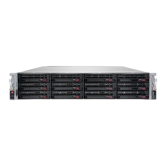
Page 14: Wf-500-B Front Panel
WF-500-B Appliance Overview WF-500-B Front Panel The following image shows the front panel of the WF-500-B appliance and the table describes each front panel component. Item Component Description Power button Press this button to power on or power off the appliance. - Page 15 Panel.) Hard-disk drives (HDDs) Disk drive bays and HDDs used for log storage. By default, the WF-500-B ships with four HDDs installed in drive bays A1/A2 and B1/B2. You can install up to eight additional drives (four additional RAID 1 pairs) in the remaining drive bays (C1/C2, D1/D2, E1/E2, and F1-F2) to increase log storage capacity.
-
Page 16: Wf-500-B Back Panel
WF-500-B Appliance Overview WF-500-B Back Panel The following image shows the back panel of the WF-500-B appliance and the table describes each back panel component. Item Component Description System drive 480GB solid-state drive (SSD) used to store the operating system files and system logs. - Page 17 The back-panel UID LED is located to the right of the UID button. Push the UID button again to deactivate these LEDs. WF-500-B Appliance Hardware Reference 2023 Palo Alto Networks, Inc. ©...
- Page 18 Administrator’s Guide on the ™ Technical Documentation Portal for the release running on your appliance. If the appliance is in PAN-DB mode, refer to the appropriate release- specific PAN-OS Administrators Guide. ® WF-500-B Appliance Hardware Reference 2023 Palo Alto Networks, Inc. ©...
-
Page 19: Install The Wf-500-B Appliance
Install the WF-500-B Appliance The following topics describe how to install and set up the WF-500 appliance. > Install the WF-500-B Appliance in a 19" Equipment Rack > Connect Power to the WF-500-B Appliance... -
Page 20: Install The Wf-500-B Appliance In A 19" Equipment Rack
Install the WF-500-B Appliance in a 19" Equipment Rack The WF-500-B appliance ships with a rack mount kit that includes two sets of rail assemblies required to install the appliance in a 4-post rack. This rail kit will fit a rack between 26.5” and 36.4”... - Page 21 Install the WF-500-B Appliance appliance to engage the hooks. Secure the back part of each rail to the appliance using one M4 screw for each rail. The inner-rails also use a pressure-lock clip (one on each rail) that locks the rails to the appliance.
- Page 22 Install the WF-500-B Appliance (with washers) for each rail. The following image shows the right side of the rack if you are facing the front of the rack. WF-500-B Appliance Hardware Reference 2023 Palo Alto Networks, Inc. ©...
- Page 23 Install the WF-500-B Appliance STEP 3 | Install the appliance in to the equipment rack by sliding the inner-rails in to the outer rack- mount rails until the appliance stops (about halfway in to the rack). Push the inner-rail release...
- Page 24 Install the WF-500-B Appliance appliance in to the rack until the front of the appliance is flush with the front of the rack. The inner-rail release clips are shown in step 1. WF-500-B Appliance Hardware Reference 2023 Palo Alto Networks, Inc.
- Page 25 Install the WF-500-B Appliance WF-500-B Appliance Hardware Reference 2023 Palo Alto Networks, Inc. ©...
- Page 26 Install the WF-500-B Appliance STEP 4 | Secure the front of the appliance to the rack by turning the front thumb screws on each rail clockwise until tight. WF-500-B Appliance Hardware Reference 2023 Palo Alto Networks, Inc. ©...
-
Page 27: Connect Power To The Wf-500-B Appliance
To power on the WF-500-B appliance, plug two power cables into grounded wall outlets and then attach them to each of the two power supplies on the back of the WF-500-B appliance. It is recommended that you connect the power supplies to separate circuits. The device will power on automatically. - Page 28 Install the WF-500-B Appliance WF-500-B Appliance Hardware Reference 2023 Palo Alto Networks, Inc. ©...
-
Page 29: Service The Wf-500-B Appliance
This chapter describes how to replace disk drives, interpret LEDs, and troubleshoot hardware problems. For more information, see the following topics. > Interpret the WF-500-B LEDs > Replace a WF-500-B Log Drive > Replace a WF-500-B System Drive > Replace a WF-500-B Power Supply... -
Page 30: Interpret The Wf-500-B Leds
Service the WF-500-B Appliance Interpret the WF-500-B LEDs The following table describes the meaning of each Ethernet port LED on the appliance. Each Ethernet port on the WF-500-B appliance has two LEDs — one on the left and one on the right. Description Left •... -
Page 31: Replace A Wf-500-B Log Drive
Service the WF-500-B Appliance Replace a WF-500-B Log Drive The WF-500-B appliance log drives are located on the front of the appliance. Each drive pair (A1 and A2 for example) is in an independent RAID 1 array. This redundant configuration helps ensure that there is no service interruption or loss of log data if a disk drive fails. - Page 32 Service the WF-500-B Appliance STEP 3 | Press the ejector button on the carrier of the failed drive (A2 in this example) to release the carrier handle and gently pull the handle toward you and slide the carrier out of the appliance.
- Page 33 Service the WF-500-B Appliance will cause the lever to close part way. When the drive carrier is almost fully inserted, close the lever to seat the drive. 3. Add the replacement drive to the RAID 1 array. In this example, run the following command to add drive A2 to the array: admin@hostname>...
- Page 34 Service the WF-500-B Appliance will cause the lever to close part way. When the drive carrier is almost fully inserted, close the lever to seat the drive. 3. Copy the data from the existing drive in the RAID 1 array to the replacement drive. In this example, run the following command to copy the data from drive A1 to drive A2: admin@hostname>...
-
Page 35: Replace A Wf-500-B System Drive
For assistance in verifying the status of the drive to determine if it should be replaced, contact Palo Alto Networks Support. The system drive on the WF-500-B appliance is located on the back panel of the appliance (see WF-500-B Back Panel). Disconnect all power cords before servicing the WF-500-B appliance. - Page 36 Service the WF-500-B Appliance STEP 4 | Install the replacement drive in the drive carrier of the failed drive. 1. Place the failed drive next to the replacement drive with the connectors facing the same direction. 2. Remove the four screws that hold the failed drive in the carrier and remove the drive from the carrier.
- Page 37 Service the WF-500-B Appliance STEP 5 | Install the replacement drive in the appliance. 1. Ensure that the drive carrier lever is in the open position; if it is not, press the ejector button on the drive carrier to release the lever and pull it out until it is fully open.
-
Page 38: Replace A Wf-500-B Power Supply
Service the WF-500-B Appliance Replace a WF-500-B Power Supply The WF-500-B appliance has two AC power supplies (the second power supply is for redundancy). If one power supply fails, you can replace it without service interruption as described in the following procedure. -
Page 39: Wf-500-B Appliance Specifications
WF-500-B Appliance Specifications The following topics describe the WF-500-B appliance hardware specifications. > WF-500-B Physical Specifications > WF-500-B Electrical Specifications > WF-500-B Environmental Specifications... -
Page 40: Wf-500-B Physical Specifications
WF-500-B Appliance Specifications WF-500-B Physical Specifications The following table describes the WF-500-B appliance physical specifications. Specification Value • Rack unit—2U Rack units (U) and dimensions • Dimensions—3.5” H x 28.46” D x 17.2” W (8.89cm H x 72.29cm D x 43.69cm W) Weight •... -
Page 41: Wf-500-B Electrical Specifications
WF-500-B Appliance Specifications WF-500-B Electrical Specifications The following table describes the WF-500-B appliance electrical specifications. Specification Value Power Supplies Two 1200W AC power supplies; the second power supply is for redundancy. Input voltage and frequency 100-240VAC (50-60Hz) Power consumption 486W Maximum current consumption 9.5A@100VAC, 4.5A@240VAC... -
Page 42: Wf-500-B Environmental Specifications
WF-500-B Appliance Specifications WF-500-B Environmental Specifications The following table describes the WF-500-B appliance environmental specifications. Specification Value Operating temperature range 41ºF to 104ºF (5ºC to 40ºC) Non-operating temperature -40ºF to 140ºF (-40ºC to 60ºC) • Operating relative humidity (non- Humidity tolerance condensing)—8% to 90%... -
Page 43: Wf-500-B Appliance Hardware Compliance Statements
Our products meet standards for product safety and electromagnetic compatibility when used for their intended purpose.To view compliance statements for the WF-500-B appliance, see WF-500-B Compliance Statements. -
Page 44: Wf-500-B Compliance Statements
WF-500-B Appliance Hardware Compliance Statements WF-500-B Compliance Statements This section provides the compliance statement for the Voluntary Control Council for Interference by Information Technology Equipment (VCCI), which governs radio frequency emissions in Japan. The following information is in accordance to VCCI Class A requirements: Translation: This is a Class A product.
Need help?
Do you have a question about the WF-500-B and is the answer not in the manual?
Questions and answers