Advertisement
Quick Links
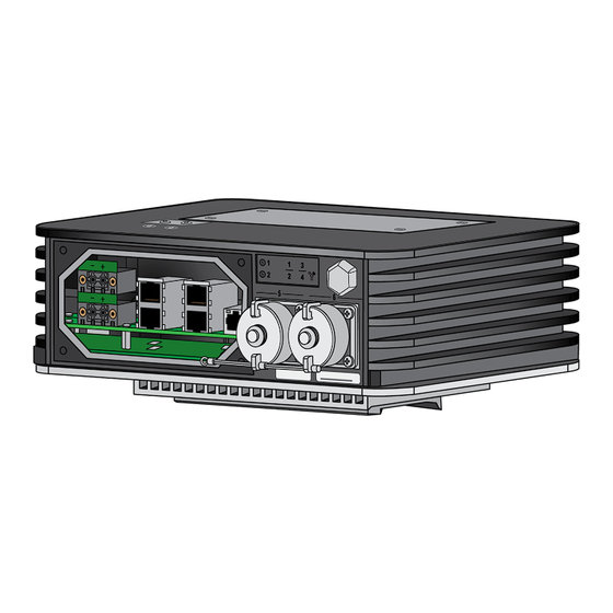
PA-410R
1
Before You Begin
Use this document to install and begin setting up your Palo Alto Networks PA-410R device. Refer to the product's hardware
reference at
https://docs.paloaltonetworks.com/hardware
for installing the firewall.
◼
Verify that the installation site has adequate air circulation and DC power.
◼
Have the following equipment ready:
◼
1/8" flat head screwdriver for terminal block screws.
◼
Crimp tool for #10 ground lug and 8 AWG wire.
◼
Wire strippers for 8 AWG and 16 AWG wire.
◼
Unpack the equipment and verify that you received the following items:
Qty
Description
1
PA-410R firewall.
2
DC terminal block and connector.
1
#10 Ground lug.
1
USB to Micro-USB Console cable.
1
Shielded RJ-45 CAT6 Ethernet cable for management (MGT) port access.
1
DIN rail clip.
4
M4 screws.
1
Sheet, Limited Warranty.
1
China RoHS declaration.
1
End User License Agreement (EULA).
2
Connect the Ethernet Cables
The PA-410R requires the installation of cable glands and waterproof cabling (purchased separately) to ensure that the device
remains safe in harsh conditions.
You must have purchased PAN-PA-RGD-GLND1 or have access to other standard M12 cable glands to complete this step.
1 Using a flat/Phillips combo screwdriver, unscrew the four screws on the bottom panel of the firewall.
2 On the removed panel, unscrew the stopping plug that lines up with the Ethernet port you are connecting to.
docs.paloaltonetworks.com
for safety information, specifications, and more detailed procedures
(Figure
Figure 1
Figure 2
3 Unpack the Ethernet cable glands. There are four items — an end cap, panel connector, seal, and grommet.
3)
(Figure
If using your own cable glands, ensure that your seal corresponds to the diameter of your Ethernet cable.
4 Install the seal onto the shorter end of the panel connector. Make sure to push the seal until it is flush against the
connector. Screw the shorter end of the panel connector into the hole that corresponds to the Ethernet port being
connected. Make sure that the connector is secure by torquing to 2 Nm.
1)
5 Thread the (unterminated) Ethernet cable through the end cap. This is used to secure the cable gland once the panel is
reattached at the end of
panel connector, terminate the cable end, and gently push it into the Ethernet port until you hear a click.
2)
(Figure
2.2
6 Repeat Steps
through
7 Leave the front panel removed and continue to
Page 1 of 4
Quick Start Guide
Figure 3
Cable Diameter
Seal
4.8 - 6.2 mm
5.0 mm
7.3 - 9.0 mm
8.5 mm
6.0 - 7.5 mm
6.7 mm
4.8 - 9.0 mm
5.0 / 8.5 / 6.7 mm
4)
(Figure
Figure 4
Step 3
. Feed the Ethernet cable through the gray grommet. Move the Ethernet cable through the
Figure 5
2.5
for any additional Ethernet cables.
Step 3 — Connect the Power Cables
5)
(Figure
Advertisement

Subscribe to Our Youtube Channel
Related Manuals for PaloAlto Networks PA-410R


Summary of Contents for PaloAlto Networks PA-410R
- Page 1 3 Unpack the Ethernet cable glands. There are four items — an end cap, panel connector, seal, and grommet. (Figure Use this document to install and begin setting up your Palo Alto Networks PA-410R device. Refer to the product’s hardware reference at https://docs.paloaltonetworks.com/hardware...
- Page 2 PA-410R QUICK START GUIDE (CONTINUED) Connect the Power Cables Connect one end of a 8 AWG ground cable (not included) to the dual-hole ground lug. Connect the other end of the cable to earth ground. Remove the two ground screws from the ground point on the front panel of the firewall. Hold the ground lug (that you previously attached to the ground cable) over the screw holes, and then re-attach the screws to secure the cable to the firewall.
- Page 3 PA-410R QUICK START GUIDE (CONTINUED) Connect the Fiber Cables Connect the fiber cable to the installed transceiver. Move the three cable gland components towards the firewall. Push the seal into the connector. (Figure You must have purchased PAN-PA-RGD-GLND2 to complete this step.
- Page 4 Start here to Register and Set Up your firewall and access all resources and support tools: https://go.paloaltonetworks.com/CustomerLaunchPad The PA-410R firewall has a 100 x 100 VESA mount pattern and makes use of four M4 screws. The VESA mount itself must be purchased separately.
Need help?
Do you have a question about the PA-410R and is the answer not in the manual?
Questions and answers