Table of Contents
Advertisement
Quick Links
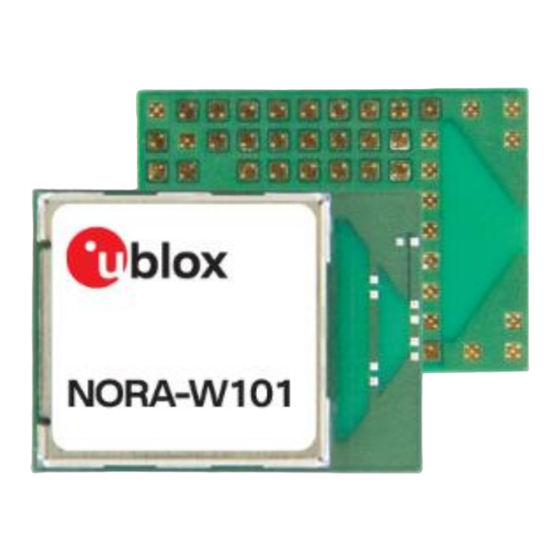
NORA-W10 series
Standalone, multiradio modules with Wi-Fi 4
(802.11b/g/n) and Bluetooth Low Energy 5.0
System integration manual
Abstract
This manual provides a functional overview combined with best-practice design guidelines for
integrating NORA-W10 stand-alone Wi-Fi and Bluetooth Low Energy v5.0 modules in customer
applications. Including a powerful microcontroller, MCU, NORA-W10 is intended for custom
application software. The module has several important embedded security features, including
secure boot, which ensures the module boots with authenticated software only.
UBX-22005601 - R04
C1-Public
www.u-blox.com
Advertisement
Table of Contents

Subscribe to Our Youtube Channel
Related Manuals for u-blox NORA-W10 Series


Summary of Contents for u-blox NORA-W10 Series
- Page 1 NORA-W10 series Standalone, multiradio modules with Wi-Fi 4 (802.11b/g/n) and Bluetooth Low Energy 5.0 System integration manual Abstract This manual provides a functional overview combined with best-practice design guidelines for integrating NORA-W10 stand-alone Wi-Fi and Bluetooth Low Energy v5.0 modules in customer applications.
-
Page 2: Document Information
[2]. u-blox or third parties may hold intellectual property rights in the products, names, logos and designs inclu ded in this document. Copying, reproduction, or modification of this document or any part thereof is only permitted with the express written permission of u-blox. -
Page 3: Table Of Contents
NORA-W10 series - System integration manual Contents Document information ........................2 Contents ..............................3 Module overview ..........................6 1.1 Module architecture ............................6 1.1.1 Block diagram ............................. 7 1.2 Pin definition ................................ 8 1.2.1 General Purpose Input and Output, GPIO pins.................. 8 1.3 Pin assignment ..............................8 1.4 Pin list.................................. - Page 4 NORA-W10 series - System integration manual 3.4.2 Component placement .......................... 25 3.4.3 Layout and manufacturing ........................25 3.5 Module footprint and paste mask ....................... 26 3.6 Thermal guidelines............................27 3.7 ESD guidelines..............................27 3.8 Design-in checklists............................28 3.8.1 Schematic checklist..........................28 3.8.2...
- Page 5 NORA-W10 series - System integration manual 6.5.2 End product labelling requirement ..................... 42 6.5.3 End product user manual requirement ..................... 43 6.6 NCC Taiwan compliance ..........................43 6.6.1 Taiwan NCC Warning Statement ....................... 43 6.6.2 Labeling requirements for end product .................... 43 6.7 KCC South Korea compliance ........................
-
Page 6: Module Overview
NORA-W10 series - System integration manual Module overview The NORA-W10 series comprises small, stand-alone, multiradio modules that integrate a powerful microcontroller, MCU, and a radio for wireless Bluetooth and Wi-Fi communication. With the open CPU architecture, customers can develop advanced applications running on the dual core 32-bit MCU. The radio provides support for Wi-Fi 802.11b/g/n in the 2.4 GHz ISM band and Bluetooth Low Energy (LE) -
Page 7: Block Diagram
NORA-W10 series - System integration manual 1.1.1 Block diagram NORA-W1 ESP32-S3 VCC (3.0- 3.6V) Linear voltage regulators VCC_IO ANT PAD Wi-Fi Reset baseband (NORA-W101) UART GPIO Bluetooth LE Baseband Cryptographic hardware accelerators Quad/Octal SPI PCB trace antenna Flash (NORA-W106) (8MB) -
Page 8: Pin Definition
NORA-W10 series - System integration manual 1.2 Pin definition 1.2.1 General Purpose Input and Output, GPIO pins NORA-W101/NORA-W106 modules have 82 pins. 38 pins can be used for either input or output. 4 pins are for input only. 1.3 Pin assignment Figure 2 shows the multiplexed pinout for NORA-W101 and NORA-W106 Open CPU modules. -
Page 9: Pin List
NORA-W10 series - System integration manual 1.4 Pin list Table 2 describes the common pinout for all NORA-W10 series modules. NORA function I/O Description ESP32-S3 Remarks function FSPIWP / SPI2 Write Protect / FSPIWP / GPIO38 General Purpose I/O GPIO38... - Page 10 NORA-W10 series - System integration manual NORA function I/O Description ESP32-S3 Remarks function USB_N / USB differential data signal / USB_D- / Analog-capable pin. Default drive capability of this pin is ~40mA GPIO19 General Purpose I/O GPIO19 SPICS1 SPI Chip select / SPICS1 / PSRAM chip select.
- Page 11 NORA-W10 series - System integration manual NORA function I/O Description ESP32-S3 Remarks function GPIO5 General Purpose I/O GPIO5 Analog-capable pin, Touch button input GPIO3 General Purpose I/O GPIO3 Analog-capable pin, Touch button input Antenna Tx/Rx interface LNA_IN 50 Ω nominal characteristic impedance, only used with NORA-W101 modules.
-
Page 12: Module Integration
Low Power mode with Low Frequency Clock NORA-W10 series modules do not have an internal low power oscillator (LPO) or low frequency crystal (LFXTAL), which is required for low power modes. If low power mode is required, an external high precision, +/- 20 ppm, 32.768 kHz crystal must be connected between pins XTAL_32K_N (Pin B6) and... -
Page 13: Module Supply Input (Vcc)
NORA-W10 modules currently support 3.0–3.6 V IO voltage level only. 2.3.3 VCC application circuits The power for NORA-W10 series modules is applied through the VCC pins. These supplies are taken from either of the following sources: • Switching Mode Power Supply (SMPS) •... -
Page 14: Antenna Integration
Figure Figure 4: Button on Boot pin 2.6 Antenna integration Antenna interfaces are different for each module variant in the NORA-W10 series. The modules support either an internal antenna (NORA-W106) or external antennas connected through a dedicated antenna pin (NORA-W101). -
Page 15: Internal Antenna
Reference designs are available on request from u-blox. The designer integrating a u-blox reference design into an end-product is solely responsible for any unintentional RF emission generated by the end product. The module may be integrated with other antennas. In which case, the OEM installer must certify the design with respective regulatory agencies. -
Page 16: Dual/Quad Spi
NORA-W10 series - System integration manual It is possible to connect the remaining SPI interfaces to other pins via the IO MUX but the maximum speed will be reduced. It is also possible to configure the SPI interface as a dual or quad SPI (2 or 4-bit bidirectional data signals). -
Page 17: Design-In
NORA-W10 series - System integration manual Design-in Follow the design guidelines stated in this chapter to optimize the integration of NORA-W10 series modules in the final application board. 3.1 Overview Although all application circuits must be properly designed, there are several points that require special attention during application design. -
Page 18: Rf Transmission Line Design (Nora-W101)
⚠ When integrating the u-blox reference design into an end-product, the application designer is solely responsible for any unintentional emission levels produced by the end-product. - Page 19 NORA-W10 series - System integration manual Figure 6 shows the design options for implementing a transmission line, namely: • Microstrip – track separated with dielectric material and coupled to a single ground plane. • Coplanar microstrip – track separated with dielectric material and coupled to both the ground plane and side conductor.
-
Page 20: Antenna Design (Nora-W101)
NORA-W101 module with all the applicable required certification schemes heavily depends on the radiating performance of the antennas. The designer is encouraged to consider one of the u-blox suggested antenna part numbers and follow the layout requirements. • External antennas such as linear monopole: External antennas basically do not imply physical restriction to the design of the PCB where the module is mounted. - Page 21 NORA-W10 series - System integration manual • Integrated antennas such as patch-like antennas: Internal integrated antennas imply physical restriction to the PCB design: Integrated antenna excites RF currents on its counterpoise, typically the PCB ground plane of the device that becomes part of the antenna; its dimension defines the minimum frequency that can be radiated.
- Page 22 NORA-W10 series - System integration manual Observe the following recommendations while selecting external or internal antennas: • Select antennas that provide optimal return loss or Voltage Standing Wave Ratio (VSWR) over all the operating frequencies. • Select antennas that provide optimal efficiency over all operating frequencies.
-
Page 23: On-Board Antenna Design
The NORA-W106 has six extra GND pads under the antenna that need to be connected for a good antenna performance. Detailed measurements of the footprint including this extra GND pads can be found in the NORA-W10 series datasheet [2]. •... - Page 24 NORA-W10 series - System integration manual • The module shall be placed such that the antenna faces outwards from the product and is not obstructed by any external items in close vicinity of the products intended use case. Figure 7: GND plane guard area enclosing NORA-W106...
-
Page 25: Data Communication Interfaces
NORA-W10 series - System integration manual 3.3 Data communication interfaces 3.3.1 Asynchronous serial interface (UART) design The layout of the UART bus should be done so that noise injection and cross talk are avoided. It is advisable to use the hardware flow control with RTS/CTS to prevent temporary UART buffer overrun. -
Page 26: Module Footprint And Paste Mask
NORA-W10 series - System integration manual • Ensure to track your impedance matched traces. Consult early with your PCB manufacturer for proper stack-up definition. • RF, analog, and digital sections should have dedicated and clearly separated areas on the board. -
Page 27: Thermal Guidelines
Figure 3.6 Thermal guidelines The NORA-W10 series modules have been successfully tested in -40 °C to +85 °C. A good grounding should be observed for temperature relief during high ambient temperature. 3.7 ESD guidelines The immunity of devices integrating NORA-W10 modules to Electro-Static Discharge (ESD) is part of the Electro-Magnetic Compatibility (EMC) conformity, which is required for products bearing the CE marking, compliant with the R&TTE Directive (99/5/EC), the EMC Directive (89/336/EEC) and the Low... -
Page 28: Design-In Checklists
PCB stack-up and controlled impedance traces follow the recommendations given by the PCB manufacturer. All pins are properly connected, and the footprint follows u-blox pin design recommendations. Proper clearance has been provided between the RF and digital sections of the design. -
Page 29: Software
NORA-W10 series - System integration manual Software 4.1 SDK for Open CPU modules As NORA-W10 Open CPU modules are delivered without flashed software, you develop your application design using the utilities and device-level APIs supported by the module chipset supplier. -
Page 30: Set Up Toolchain And Esp-Idf V4.4 Source Files
NORA-W10 series - System integration manual Use the following workflow setup to compile, flash, and execute a program on NORA-W10: Set up Toolchain and ESP-IDF v4.4 source files Windows, Mac, and Linux are supported. 2. Get ESP-IDF. Download the GIT repository provided by Espressif Setup path to ESP-IDF. -
Page 31: Esp-Idf Partition Table
NORA-W10 series - System integration manual In the following example, only the com port that is used to flash NORA-W10 is modified. 6. Exit the configuration window by pressing “Q” and confirm save the configuration. Now the project is ready to build. -
Page 32: Automatic Bootloader On Nora-W10 Evk
4.3.1.1 Wi-Fi output power configuration for version v4.4 The components required to perform the output power configuration and RF calibration are included (with examples) under the product subfolder in the u-blox SHO-OpenCPU GitHub repository [9]. 4.3.1.2 Bluetooth low energy output power configuration No output power configuration for Bluetooth low energy is required. -
Page 33: Handling And Soldering
No natural rubbers, hygroscopic materials or materials containing asbestos are employed. ⚠ NORA-W10 series modules are Electrostatic Sensitive Devices that demand the observance of special handling precautions against static damage. Failure to observe these precautions can result in severe damage to the product. -
Page 34: Reflow Soldering Process
The thickness of solder resist between the host PCB top side and the bottom side of the NORA-W10 series module must be considered for the soldering process. -
Page 35: Cleaning
NORA-W10 series - System integration manual 5.3.1 Cleaning Cleaning the modules is not recommended. Residues underneath the modules cannot be easily removed with a washing process. • Cleaning with water will lead to capillary effects where water is absorbed in the gap between the baseboard and the module. -
Page 36: Regulatory Compliance
NORA-W10 modules are approved for use. Each market has its own regulatory requirements that must be fulfilled, and NORA-W10 series modules must comply with the requirements for a radio transmitter in each of the listed markets. -
Page 37: Great Britain Regulatory Compliance
This device complies with Part 15 of the FCC Rules and with Industry Canada license-exempt RSS standard(s). Any changes or modifications NOT explicitly APPROVED by u-blox AG may cause the module to not comply with the FCC rules part 15 thus void the user's authority to operate the equipment. -
Page 38: Configuration Control And Software Security Of End-Products
SAR evaluation and/or testing. Any changes or modifications NOT explicitly APPROVED by u-blox may cause the NORA-W10 series module to cease to comply with the FCC rules part 15 thus void the user’s authority to operate the equipment on the US market. -
Page 39: Operating Frequencies
NORA-W10 series - System integration manual ☞ OET KDB 594280 D02 [12] lists the topics that must be addressed to ensure that the end- product specific host meets the Software Security Requirements for U-NII Devices. 6.4.3 Operating frequencies NORA-W10 802.11b/g/n operation outside the 2412–2462 MHz band is prohibited in the US and Canada. -
Page 40: End-Product User Manual Instructions
WLAN capability is turned off and only the Bluetooth LE capability of NORA-W10 is utilized. ☞ KDB 996369 D03 section 2.4 (limited module procedures) is not applicable to NORA-W10 series modules. ☞ KDB 996369 D03 section 2.5 (trace antenna designs) is not applicable to NORA-W10 series modules. -
Page 41: End-Product Compliance
• Any notification to the end user about how to install or remove the integrated radio module is NOT allowed. • The approval of the modular transmitter in NORA-W10 series modules does not exempt the end product from being evaluated against any applicable regulatory demands. The evaluation of the end product shall be performed with the NORA-W10 module installed and operating in a way that reflects the intended use case of the end product. -
Page 42: Japan Radio Equipment Compliance
Item 19 "2.4 GHz band wide band low power data communication system". 6.5.2 End product labelling requirement End products based on NORA-W10 series modules and targeted for distribution in Japan must be affixed with a label with the “Giteki” marking, as shown in Figure 14. -
Page 43: End Product User Manual Requirement
ISM radio wave radiated devices. 6.6.2 Labeling requirements for end product End products based on NORA-W10 series modules and targeted for distribution in Taiwan must carry labels with the textual and graphical elements shown below. -
Page 44: Kcc South Korea Compliance
NORA-W10 series modules are certified by the Korea Communications Commission (KCC). End products based on NORA-W10 series modules and targeted for distribution in South Korea must carry labels containing the KCC logo and certification number, as shown below. This information must also be included in the product user manuals. -
Page 45: Australia And New Zealand Regulatory Compliance
⚠ Approvals are pending for NORA-W101 and NORA-W106. NORA-W10 series modules are compliant and certified by the Independent Communications Authority of South Africa (ICASA). End products that are made available for sale or lease or supplied in any other manner in South Africa shall have a legible label permanently affixed to its exterior surface. -
Page 46: Bluetooth Qualification
QDID for the Bluetooth stack implemented in the Host Subsystem with the QDID of the pre-qualified Controller Subsystem shown in Table Product type QDID Listing date Controller Subsystem 198070 2022-11-14 Table 113: NORA-W10 series Bluetooth qualified design ID UBX-22005601 - R04 Regulatory compliance Page 46 of 56 C1-Public... -
Page 47: Pre-Approved Antennas List
Comment The Reverse Polarity SMA connector can be mounted in a panel. See NORA-W10 Series system integration manual [2] for information about how to integrate the U.FL connector. This reference design must be followed to comply with the NORA-W10 FCC/IC modular approvals. -
Page 48: Single Band Antennas
NORA-W10 series - System integration manual 7.2 Single band antennas NORA-W106 internal antenna Manufacturer Abracon Gain +3 dBi Impedance Size (HxWxL) 1.1 x 3.4 x 10 mm Type PCB trace Comment PCB antenna on NORA-W106. The antenna should not be mounted inside a metal enclosure. - Page 49 NORA-W10 series - System integration manual Wi-Fi / Bluetooth external antenna, PN PRO-EX-296 Manufacturer Abracon Polarization Vertical Gain +2.0 dBi Impedance 50 Ω Size Ø 12.0 x 28.0 mm Type Monopole Cable length 100 mm Connector U.FL. connector Comment This antenna requires to be mounted on a metal ground plane for best performance.
-
Page 50: Dual-Band Antennas
NORA-W10 series - System integration manual Wi-Fi / Bluetooth / Bluetooth LE board antenna, PN PRO-IS-237 Manufacturer Abracon Gain +3.0 dBi Impedance 50 Ω Size 27 x 12 mm (triangular) Type Patch Cable length 100 mm Connector U.FL. connector Comment Should be attached to a plastic enclosure or part for best performance. - Page 51 NORA-W10 series - System integration manual Wi-Fi / Bluetooth exernal whip antenna, PN PRO-EX-286 Manufacturer Abracon Polarization Vertical Gain +3 dBi Impedance 50 Ω Size 107 mm (Straight) Type Monopole Connector Reverse Polarity SMA plug (inner thread and pin receptacle) Comment To be mounted with a U.FL to Reverse Polarity SMA adapter cable.
-
Page 52: Product Testing
Product testing 8.1 u-blox in-line production test As part of our focus on high quality products, u-blox maintain stringent quality controls throughout the production process. This means that all units in our manufacturing facilities are fully tested and that any identified defects are carefully analyzed to improve future production quality. -
Page 53: Oem Manufacturer Production Test
NORA-W10 series - System integration manual 8.2 OEM manufacturer production test As all u-blox products undergo thorough in-series production testing prior to delivery, OEM manufacturers do not need to repeat any firmware tests or measurements that might otherwise be necessary to confirm RF performance. Testing over analog and digital interfaces is also unnecessary during an OEM production test. -
Page 54: Appendix
NORA-W10 series - System integration manual Appendix A Glossary Abbreviation Definition Automotive Electronics Council Access Point Application Programming Interface Automatic Test Equipment Charged Device Model European Conformity Clear to Send Don’t Care Direct Current Double Data Rate Dynamic Frequency Selection... - Page 55 NORA-W10 series - System integration manual Abbreviation Definition PCIe PCI Express Pulse-code modulation Physical layer (of the OSI model) Power Management Unit Radio Frequency RSDB Real Simultaneous Dual Band Request to Send SDIO Secure Digital Input Output Solder Mask Defined...
-
Page 56: Related Documentation
594280 D01 Configuration Control v02 r01 [14] EN 62368-1 - Audio/video, information and communication technology equipment - Part 1: Safety requirements ☞ For product change notifications and regular updates of u-blox documentation, register on our website, www.u-blox.com. Revision history Revision...
Need help?
Do you have a question about the NORA-W10 Series and is the answer not in the manual?
Questions and answers