Table of Contents
Advertisement
Quick Links
Advertisement
Table of Contents

Related Manuals for u-blox C94-M8P


Summary of Contents for u-blox C94-M8P
- Page 1 C94-M8P u-blox RTK Application Board Package User Guide Abstract This document describes the structure and use of the C94-M8P RTK application board package and provides information for evaluating and testing u-blox NEO-M8P high precision positioning modules. www.u-blox.com UBX-15031066 - R07...
- Page 2 The information contained herein is provided “as is” and u-blox assumes no liability for the use of the information. No warranty, either express or implied, is given, including but not limited, with respect to the accuracy, correctness, reliability and fitness for a particular purpose of the information.
-
Page 3: Preface
“Directive 2002/95/EC and Directive 2011/65/EU of the European Parliament and the Council on the Restriction of Use of certain Hazardous Substances in Electrical and Electronic Equipment” (RoHS). C94-M8P application board is RoHS compliant. Preface UBX-15031066 - R07 Early Production Information... -
Page 4: Table Of Contents
C94-M8P - User Guide Contents Preface ..........................3 Using this guide ............................... 3 Warnings and certifications ..........................3 Contents ..........................4 Introduction ........................7 Overview .............................. 7 C94-M8P package ..........................7 Software requirements ......................... 7 System requirements ..........................7 Specification ......................... 8 Getting started ...................... - Page 5 Updating C94 radio modem firmware ..............39 Updating procedure..........................40 Please download the correct firmware for your C94 variant from the u-blox GitHub website: https://github.com/u-blox/C94-application-board-radio-firmware/ ..............40 There are two parts to the firmware, a Boot loader (BL) and the Firmware itself (FW)........40 D Notes on FW3.01 HPG1.40 ..................
- Page 6 C94-M8P - User Guide Related documents......................46 Revision history ........................ 46 Contact ..........................47 Contents UBX-15031066 - R07 Early Production Information Page 6 of 47...
-
Page 7: Introduction
The C94-M8P board integrates the NEO-M8P-2 module with both Base Station and Rover functionality. The C94-M8P includes a UHF radio link, allowing for easy setup and fast prototyping. The board also provides connector pins, enabling a simple wired connection or communication alternatives using u-blox cellular and short-range technologies. -
Page 8: Specification
5 V via USB or externally powered by battery (5.05 mm pitch 2-pin, 3.7 V – 20 V) powered 1 battery connector Normal Operating temperature -40 °C to +65 °C Table 1: C94-M8P application board specification Specification UBX-15031066 - R07 Early Production Information... -
Page 9: Getting Started
If you have received C94-M8P-E PCB variants these units will have the latest HPG1.40 firmware on the NEO-M8P and the latest production radio modem firmware. If you are intending to use a wired RTCM3 serial connection, the radio firmware will not need updating. -
Page 10: Hardware Installation
C94-M8P - User Guide 3.3 Hardware installation To test and evaluate the benefits of u-blox Real Time Kinematic (RTK) technology, two C94-M8P application boards – “Base” and “Rover” – need to be set up as described below. Connect the UHF antenna to the SMA connector marked with “UHF”... -
Page 11: Configuration
For GNSS module configuration, use the micro-A USB port to connect with a PC running u-center. Once it is connected, configure the module on u-center (View -> Message View -> UBX-CFG-GNSS) as shown in Figure 1. For more information, refer to the u-center User Guide [4], and u-blox 8 / u-blox M8 Receiver Description including Protocol Specification [1]. -
Page 12: Base Station Operation
ECEF or Lat/Lon/Alt coordinates. The corresponding fields are shown in Figure 2 below. The parameter fields allow coordinate specification up to 0.1 mm resolution. For more information, see the u-blox 8 / u-blox M8 Receiver Description including Protocol Specification [1]. - Page 13 C94-M8P - User Guide The second field, “Required Position Accuracy”, forces the calculated Base station position to be of at least the given 3D position accuracy. This 3D position accuracy is derived estimate from the survey algorithm. This can be over-estimated, the actual absolute surveyed in accuracy will be no better than approximately 1 m.
-
Page 14: Configuring Rtcm Messages
C94-M8P - User Guide Figure 4: Base Station moving from Survey-in Mode to Fixed Mode Users should be aware that the absolute accuracy derived from a survey in exercise is unlikely to be better than 1 m, even with the best antenna and sky view combination. If the antenna location is known more precisely users should use this and preset them using the fixed mode. - Page 15 C94-M8P - User Guide The NEO-M8P UART1 port is connected to the radio modem on the application board to transmit the correction data. Hence the UART1 port must be selected as the source for all RTCM messages. To do this, use the UBX-CFG- MSG messages as shown in Figure 5 and Figure 6.
-
Page 16: Neo-M8P Uart Settings For The Base
C94-M8P - User Guide 4.2.4.2 GPS + BeiDou RTCM3 message configuration Figure 6 For a GPS + BeiDou setup, enable the RTCM messages 1005, 1077, 1127. 4.2.5 NEO-M8P UART settings for the Base The GNSS module UART needs to be configured on the Base. Use the UBX-CFG-PRT message to set “Protocol in” to “none”... -
Page 17: Neo-M8P Uart Settings For The Rover
C94-M8P - User Guide In order to mitigate position jumps when switching between fixed and float modes the rover can be set to remain in float mode selected using the message UBX-CFG-DGNSS. In this mode, the Rover will estimate the ambiguities as float but will not attempt to fix them. - Page 18 C94-M8P - User Guide The CFG-TMODE3 message must be sent even though polling a CFG-TMODE3 message shows the mode is set to disable upon power-up. With Message 4072 active, message 1005 is not output even if previously enabled. A configuration flowchart shown below in Figure 9 details the procedure for enabling the default operation.
- Page 19 1087 (GLONASS observations) plus 1230 (GLONASS code-phase biases) are required. N.B. Message 1230 enables GLONASS ambiguities to be fixed. For a GPS + BeiDou GNSS configuration, 4072 (u-blox proprietary MB message) and 1077 (GPS observations), 1127 (BeiDou observations) are required. N.B. MSM7 messages are required for all moving baseline cases.
- Page 20 C94-M8P - User Guide 4.3.1.1 GPS + GLONASS RTCM3 message configuration Figure 10: For a GPS+GLONASS setup, enable the RTCM messages 4072, 1077, 1087 and 1230 on UART1 port Configuration UBX-15031066 - R07 Early Production Information Page 20 of 47...
-
Page 21: Neo-M8P Uart Settings For Base
C94-M8P - User Guide 4.3.1.2 GPS + BeiDou RTCM3 message configuration Figure 11 For a GPS+BeiDou setup, enable the RTCM messages 4072, 1077, 1127 on UART1 port 4.3.2 NEO-M8P UART settings for Base The GNSS module UART needs to be configured on the Base. Use the UBX-CFG-PRT message to set “Protocol in” to “none”... -
Page 22: Navigation Rates Supported With Moving Baseline Operation
For 1Hz operation in wireless moving baseline mode it is necessary to have the current production version of the C94 radio firmware for the radio region. See Appendix C for more details. If you have received C94-M8P-E PCB variants these units will have HPG1.40 on the M8P and the latest production radio modem firmware and will run moving baseline mode at 1Hz using the C94 radio modems. -
Page 23: Rover With Moving Baseline
C94-M8P - User Guide 4.3.4 Rover with moving baseline The Rover will switch automatically to moving baseline mode when receiving RTCM message 4072. Refer to Figure 9 for a configuration flowchart for the default mode. The following Rover NEO-M8P UART settings are required when operating in the moving baseline mode: ... -
Page 24: Operation
Figure 18: Data View shows “FLOAT” or “FIXED” on Rover Additionally, the message “UBX-NAV-RELPOSNED” in u-center shows details about the base to rover relative positions and accuracies. For more information, refer to the u-center User Guide [4], the u-blox 8 / u-blox M8 Receiver Description including Protocol Specification [1]. -
Page 25: Moving Baseline Mode
C94-M8P - User Guide Figure 19: UBX-NAV-RELPOSNED in u-center for Rover To achieve the expected accuracy of positioning with u-blox RTK technology, continued carrier phase tracking is important. 5.2 Moving baseline mode 5.2.1 Base station in operation When the Base device is in moving baseline operation the Data View in u-center will show 3D Fix mode. It will not show "TIME"... -
Page 26: Rover In Operation
These flags are used only in moving baseline mode and can be used to help monitor the RTCM3 link quality. For more information, refer to the u-center User Guide [4], and u-blox 8 / u-blox M8 Receiver Description including Protocol Specification [1]. -
Page 27: Monitoring The Quality Of The Rtcm Stream
C94-M8P - User Guide 5.3 Monitoring the quality of the RTCM stream The RTCM message stream received by the rover can be monitored for overall quality. This is a helpful facility for checking the operation in standard RTK mode and critical in moving baseline mode where the maximum message latency is 700 mS compared to 5 s for standard RTK. -
Page 28: Moving Baseline
C94-M8P - User Guide sporadic, there may be issues with the C94 radio link or the RTCM3 serial connection or the Base receiver and Rover configuration. 5.3.1 Moving baseline The UBX-NAV-RELPOSNED message and associated u-center message view shown in Figure 25 indicate if the Rover is in moving baseline RTK mode. -
Page 29: Evaluation Interfaces
Geofence status corresponds to pin 15 and the RTK status corresponds to pin 16 on the NEO-M8P-2 module. Pin 13, pin 14, pin 20 and any of the GND pins are for connecting to u-blox C027 and other application boards. It enables communication alternatives using u-blox cellular and short-range technologies. Evaluation interfaces... -
Page 30: Battery Connector
6.4 Battery connector There is a 2-pin battery connector available on the C94-M8P for connecting the board to an external battery or DC supply. This uses a standard 5.05 mm pitch 2-pin connector for supplying a 3.7-20 VDC source or external battery. -
Page 31: Gnss Antenna Connector
C94-M8P - User Guide 6.6.2 GNSS antenna connector The GNSS module SMA connector on each board is used to connect the external active GNSS antenna. This connector is marked with the text “GNSS” on the board. 6.7 Wired serial RTCM3 connection between Base and Rover To connect two C94 application boards without using the C94 radio modem a wired connection can be set up. -
Page 32: Block Diagram
C94-M8P - User Guide 7 Block diagram Figure 27: Block diagram of the C94-M8P application board Block diagram UBX-15031066 - R07 Early Production Information Page 32 of 47... -
Page 33: Board Layout
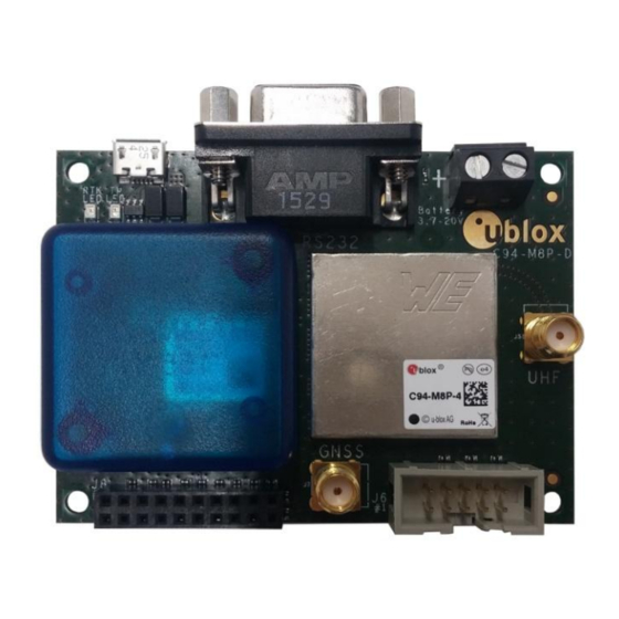
C94-M8P - User Guide 8 Board layout Figure 28: Board Layout of C94-M8P–D/E Application Board Board layout UBX-15031066 - R07 Early Production Information Page 33 of 47... -
Page 34: Schematic
C94-M8P - User Guide 9 Schematic Figure 29: Schematics of C94-M8P-E application board Schematic UBX-15031066 - R07 Early Production Information Page 34 of 47... -
Page 35: Appendix
Table 4: Explanation of abbreviations used B Radio communication link configuration Users do not need to make any configuration for the Radio communication link. The u-blox default configurations are tested and verified. Users need to take all responsibility for any changes against the default configuration. - Page 36 The u-blox default configurations of the radio modem regional variants are tested and verified. Users need to take all responsibility for any changes to the default configuration. The C94-M8P application board uses a HM-TRP radio modem with SiK open source firmware, which supports a subset variant of the Hayes “AT” modem commands for advance configuration.
- Page 37 AT commands, the radio modem returns ERROR as the response. Figure 33: Send AT commands to Radio Modem Table 6 shows the AT command set that is supported by the C94-M8P application board. Table 7 shows all radio parameters that are configurable. For more information about configuring the radio modem used by C94-M8P, see http://copter.ardupilot.com/wiki/common-3dr-radio-advanced-configuration-...
-
Page 38: Serial Console Terminal Installation
Air data rate in “one byte form”. Must be same for a pair of radios. NETID Network ID. Must be same for the pair of C94-M8P boards. Must be same for a pair of radios. TXPOWER Transmit power in dBm, maximum value is 20 dBm. -
Page 39: C Updating C94 Radio Modem Firmware
HM_TRP_006_02 HM_TRP_007_03 HM_TRP_TEST_007_04 Table 9: Current production C94 radio modem firmware versions. For units C94-M8P-X-10 (PCB C94-M8P-D) that were delivered with M8P FW HPG1.20 or lower the radio will report software versions as shown in Table 10 below: C94-M8P-1 C94-M8P-2... -
Page 40: Updating Procedure
There are two parts to the firmware, a Boot loader (BL) and the Firmware itself (FW). 1. Copy the C94 radio boot loader (BL) and firmware (FW) in the same folder as the Flash utility. For example with C94-M8P-4 the correct FW is -4 version. Example of the file names: ... -
Page 41: D Notes On Fw3.01 Hpg1.40
C94-M8P - User Guide Figure 36: Verifying radio firmware version Finally, remember to enable the GNSS module UART output when finished with radio communication link configuration. See Figure 7 and Figure 8. Ensure you also unplug any serial connection to the 9 Pin D-Type serial connector as this can interfere with the communication between the radio and the M8P. -
Page 42: For C94 Radio Firmware That Is Current Production Low Latency Firmware As Indicated In Table 9
RTCM3 data, the M8P (FW HPG1.40 only) supports higher update rates of 4 Hz at 115200 baud. E.3 C94 Variants -00 Variants using the old board version (C94-M8P-1-00, C94-M8P-2-00 and C94-M8P-3-00) have a different board layout than the C94P-M8P-X-10 versions. This chapter describes the C94P-M8P-X-00 versions and how they differ from the newer versions. -
Page 43: Dimensions
Table 11: Pin assignments of J9 J4 connector The J4 connector is the interface for connecting to u-blox C027 and other application boards. It enables communication alternatives using u-blox cellular and short-range technologies. The pin assignments of this 4-pin connector are shown in Table 12. For more details about C027, see https://www.u-blox.com/product/c027. -
Page 44: F Hardware Modification
For the C94-M8P-B: Pin 13 Figure 38: C94-M8P-B radio disable modification Capacitor C9 positive terminal (indicated by the short red line in Figure 38) needs to be connected to J8 Pin 13. Solder a short wire link between the two points indicated by the arrows. - Page 45 C94-M8P - User Guide For the C94-M8P-D and the C94-M8P-E: Pin 20 Figure 39: C94-M8P-D/E radio disable modification The plastic cover over the M8P needs to be removed first to gain access to the capacitor C9. Unscrew the two screws holding the plastic cover held in place by screws accessible from the bottom of the PCB. The two black arrows on the corners of the rectangular plastic cover indicate these screw locations.
-
Page 46: Related Documents
C94-M8P - User Guide Related documents u-blox 8 / u-blox M8 Receiver Description Including Protocol Specification (Public version), Docu. No. UBX- 13003221 NEO-M8P Data Sheet, Docu. No. UBX-15016656 NEO-M8P Hardware Integration Manual, Docu. No. UBX-15028081 u-center User Guide, Docu. No. UBX-13005250 Achieving Centimeter Level Performance with Low Cost Antennas, Docu. -
Page 47: Contact
C94-M8P - User Guide Contact For complete contact information, visit us at www.u-blox.com u-blox Offices North, Central and South America Headquarters Asia, Australia, Pacific Europe, Middle East, Africa u-blox America, Inc. u-blox Singapore Pte. Ltd. u-blox AG Phone: +1 703 483 3180...
Need help?
Do you have a question about the C94-M8P and is the answer not in the manual?
Questions and answers