Table of Contents
Advertisement
Quick Links
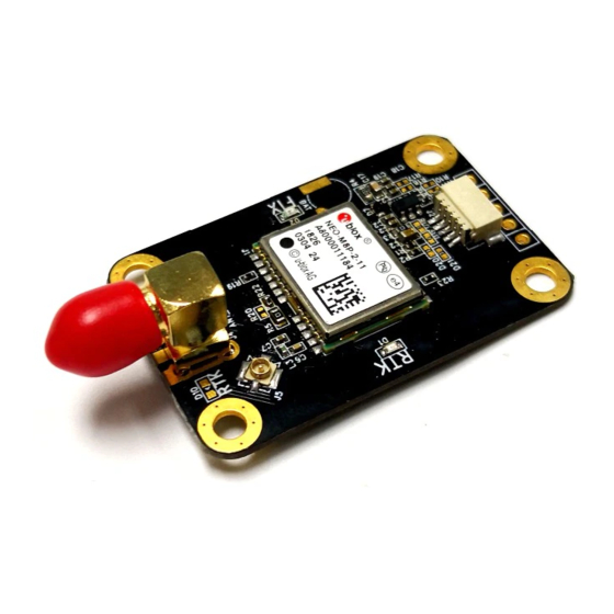
NEO-M8P
u-blox M8 High Precision GNSS Modules
Hardware Integration Manual
Abstract
This document provides design-in and feature information for the
high-accuracy NEO-M8P modules. Base and rover module variants
together provide a high precision cm-level RTK position solution. Each
module contains the u-blox M8 concurrent GNSS engine for
concurrent reception of GPS, GLONASS and BeiDou signals.
www.u-blox.com
UBX-15028081 - R05
Advertisement
Table of Contents

Related Manuals for u-blox NEO-M8P-2


Summary of Contents for u-blox NEO-M8P-2
- Page 1 This document provides design-in and feature information for the high-accuracy NEO-M8P modules. Base and rover module variants together provide a high precision cm-level RTK position solution. Each module contains the u-blox M8 concurrent GNSS engine for concurrent reception of GPS, GLONASS and BeiDou signals. www.u-blox.com...
- Page 2 The information contained herein is provided “as is” and u-blox assumes no liability for the use of the information. No warranty, either express or implied, is given, including but not limited, with respect to the accuracy, correctness, reliability and fitness for a particular purpose of the information.
-
Page 3: Table Of Contents
NEO-M8P - Hardware Integration Manual Contents Contents ..........................3 Hardware description ....................5 Overview .............................. 5 Configuration ............................5 Connecting power ..........................5 1.3.1 VCC: Main supply voltage ......................5 1.3.2 V_BCKP: Backup supply voltage ....................5 1.3.3 VDD_USB: USB interface power supply ..................6 1.3.4 VCC_RF: Output voltage RF ...................... - Page 4 NEO-M8P - Hardware Integration Manual Appendix .......................... 24 Recommended parts ........................... 24 Design-in recommendations in combination with cellular operation ........... 25 Related documents......................26 Revision history ........................ 26 Contact ..........................27 Contents UBX-15028081 - R05 Early Production Information Page 4 of 27...
-
Page 5: Hardware Description
RTK technology introduces the concept of a “rover” (NEO-M8P-0) and a “base” (NEO-M8P-2) on the M8 platform for stunning cm-level accuracy in clear sky environments. The base module sends corrections via the RTCM protocol to the rover module via a communication link enabling the rover to output its position relative to the base at cm level accuracies. -
Page 6: Vdd_Usb: Usb Interface Power Supply
1.4.1 UART NEO-M8P positioning modules include a Universal Asynchronous Receiver Transmitter (UART) serial interface RXD/TXD supporting configurable baud rates. The baud rates supported are specified in the u-blox 8 / u-blox M8 Receiver Description including Protocol Specification [2]. The signal output and input levels are 0 V to VCC. An interface based on RS232 standard levels (+/- 12 V) can be implemented using level shifters such as a Maxim MAX3232. -
Page 7: Display Data Channel (Ddc)
DDC pins SDA and SCL have internal pull-up resistors. For more information about the DDC implementation, see the u-blox 8 / u-blox M8 Receiver Description Including Protocol Specification [2]. For bandwidth information, see the NEO-M8P Data Sheet [1]. For timing parameters consult the I C-bus specification [4]. -
Page 8: I/O Pins
The pin state reflects the current Geofence status as to whether the receiver is inside any of the active areas. See the u-blox 8 / u-blox M8 Receiver Description including Protocol Specification [2] for more information. - Page 9 NEO-M8P - Hardware Integration Manual On the other hand, noise generated at the I/O pins will emit from unshielded I/O lines. Receiver performance can be degraded when this noise is coupled into the GNSS antenna (see Figure 14). To avoid interference through improperly shielded lines, it is recommended to use series resistors (e.g. R>20 Ω), ferrite beads (e.g.
-
Page 10: Design
Table 2: NEO-M8P Pinout 2.1.1 Pin name changes Selected pin names have been updated to agree with a common naming convention across u-blox modules. The pins have not changed their operation and are the same physical hardware but with updated names. The table below lists the pins that have changed name along with their old and new names. -
Page 11: Minimal Design
NEO-M8P - Hardware Integration Manual Previous Name New name ANT_ON LNA_EN TXD / SPI MISO RXD / SPI MOSI Table 3: NEO-M8P Module Pin renaming 2.2 Minimal design This is a minimal design for a NEO-M8P GNSS receiver. Figure 4: NEO-M8P passive antenna design 2.3 Layout: Footprint and paste mask Figure 5 describes the footprint and provides recommendations for the paste mask for NEO-M8P LCC modules. -
Page 12: Antenna
NEO-M8P - Hardware Integration Manual 1.0 mm [39.3 mil] Stencil: 150 µm 10.4 mm [409.5 mil] 12.2 mm [480 mil] 14.6 mm [575 mil] 12.2 mm [480.3 mil] Figure 5: NEO-M8P paste mask / NEO-M8P footprint 2.4 Antenna With RTK operation, the antenna and its placement are critical system factors, both for the Base and Rover. The minimum receiver signal strengths to track the signal phase are higher than conventional GNSS receivers, at about 34 dBHz, and require good antenna efficiency with a stable phase center. -
Page 13: Active Antenna Design
NEO-M8P - Hardware Integration Manual Use an antenna that has sufficient bandwidth to receive all GNSS constellations. See Appendix A.1. Figure 7 shows a design using an external LNA to increase the sensitivity for best performance with passive antenna. Figure 7: Module design with passive antenna and an external LNA (for exact pin orientation see the NEO-M8P Data Sheet [1]) The LNA_EN pin (LNA enable) can be used to turn on and off an optional external LNA. - Page 14 Active antenna design powered from external supply Figure 9: Active antenna design, direct external supply (for exact pin orientation see the NEO-M8P Data Sheet [1]) The circuit shown in Figure 9 works with all u-blox M8 modules, also with modules without VCC_RF output.
-
Page 15: Product Handling
NEO-M8P - Hardware Integration Manual 3 Product handling 3.1 Packaging, shipping, storage and moisture preconditioning For information pertaining to reels and tapes, Moisture Sensitivity levels (MSL), shipment and storage information, as well as drying for preconditioning see the NEO-M8P Data Sheet [1]. Population of Modules When populating the modules, make sure that the pick and place machine is aligned to the copper pins of the module and not on the module edge. - Page 16 NEO-M8P - Hardware Integration Manual Cooling phase A controlled cooling avoids negative metallurgical effects (solder becomes more brittle) of the solder and possible mechanical tensions in the products. Controlled cooling helps to achieve bright solder fillets with a good shape and low contact angle.
- Page 17 NEO-M8P - Hardware Integration Manual Repeated reflow soldering Only single reflow soldering processes are recommended for boards populated with NEO-M8P modules. NEO-M8P modules should not be submitted to two reflow cycles on a board populated with components on both sides in order to avoid upside down orientation during the second reflow cycle.
-
Page 18: Eos/Esd/Emi Precautions
EMI covers is done at the customer’s own risk. The numerous ground pins should be sufficient to provide optimum immunity to interferences and noise. u-blox makes no warranty for damages to the NEO-M8P module caused by soldering metal cables or any other forms of metal strips directly onto the EMI covers. - Page 19 NEO-M8P - Hardware Integration Manual sensitive electronics is prevented. International standards are used to define typical EPA and can be obtained for example from the International Electrotechnical Commission (IEC) or American National Standards Institute (ANSI). GNSS positioning modules are sensitive to ESD and require special precautions when handling. Particular care must be exercised when handling patch antennas, due to the risk of electrostatic charges.
- Page 20 NEO-M8P - Hardware Integration Manual Protection measure A is preferred because it offers the best GNSS performance and best level of ESD protection. Electrical Overstress (EOS) Electrical Overstress (EOS) usually describes situations when the maximum input power exceeds the maximum specified ratings.
- Page 21 NEO-M8P - Hardware Integration Manual EOS protection measures For designs with GNSS positioning modules and wireless transceivers (e.g. GSM/GPRS) in close proximity, ensure sufficient isolation between the wireless and GNSS antennas. If the wireless power output causes the specified maximum power input at the GNSS RF_IN to be exceeded, employ EOS protection measures to prevent overstress damage.
-
Page 22: Applications With Cellular Modules
Related documents for the absolute maximum power input at the GNSS receiver. See the GPS Implementation and Aiding Features in u-blox wireless modules [5]. Isolation between GNSS and GSM antenna In a handheld design, an antenna isolation of approximately 20 dB can be reached with careful placement of the antennas. - Page 23 SAW or band pass ceramic filter (as recommend in section 3) into the antenna input line to the GNSS receiver (see Figure 16). Figure 16: Measures against out-band interference For design-in recommendations in combination to Cellular operation see Appendix See the GPS Implementation and Aiding Features in u-blox wireless modules [5] Product handling UBX-15028081 - R05 Early Production Information...
-
Page 24: Appendix
NEO-M8P - Hardware Integration Manual Appendix A.1 Recommended parts Recommended parts are selected on data sheet basis only. Other components may also be used. Part Manufacturer Part ID Remarks Parameters to consider Diode ESD9R3.3ST5G Standoff Voltage>3.3 V Low Capacitance < 0.5 pF Semiconductor ESD9L3.3ST5G Standoff Voltage>3.3 V... -
Page 25: Design-In Recommendations In Combination With Cellular Operation
• = integrated = optimal performance Table 6: Combinations of u-blox GNSS modules with different cellular technologies (2G/3G/4G). See the GPS Implementation and Aiding Features in u-blox wireless modules [5]. Appendix UBX-15028081 - R05 Early Production Information... -
Page 26: Related Documents
GPS Implementation and Aiding Features in u-blox wireless modules, Doc. No. GSM.G1-CS-09007 u-blox 7 to u-blox 8 / M8 Software Migration Guide, Doc. No. UBX-15031124 For regular updates to u-blox documentation and to receive product change notifications, register on our homepage (http://www.u-blox.com) -
Page 27: Contact
NEO-M8P - Hardware Integration Manual Contact For complete contact information, visit us at www.u-blox.com u-blox Offices North, Central and South Headquarters Asia, Australia, Pacific America Europe, Middle East, Africa u-blox Singapore Pte. Ltd. Phone: +65 6734 3811 u-blox America, Inc.
Need help?
Do you have a question about the NEO-M8P-2 and is the answer not in the manual?
Questions and answers