Emerson Micro Motion 5700 Installation Manual
Ethernet transmitters
Hide thumbs
Also See for Micro Motion 5700:
- Installation manual ,
- Configuration and use manual (357 pages) ,
- Instruction manual (58 pages)

Related Manuals for Emerson Micro Motion 5700


Summary of Contents for Emerson Micro Motion 5700
- Page 1 Installation Manual MMI-20029768, Rev AF February 2023 Micro Motion ™ 5700 Ethernet Transmitters Ethernet Installations...
- Page 2 Micro Motion support center. Information affixed to equipment that complies with the Pressure Equipment Directive, can be found at Emerson.com. For hazardous installations in Europe, refer to standard EN 60079-14 if national standards do not apply.
-
Page 3: Table Of Contents
Installation Manual Contents MMI-20029768 February 2023 Contents Chapter 1 Before you begin........................5 1.1 About this document........................5 1.2 Hazard messages........................5 1.3 Related documentation......................5 Chapter 2 Planning............................. 7 2.1 Installation checklist........................7 2.2 Additional considerations for retrofitting existing installations........... 8 2.3 Power requirements........................9 2.4 5700 transmitters in Ethernet networks................10 Chapter 3 ... - Page 4 Contents Installation Manual February 2023 MMI-20029768 Micro Motion 5700 Ethernet Transmitters...
-
Page 5: Before You Begin
About this document This manual provides information on planning, mounting, wiring, and initial setup of the Micro Motion 5700 transmitter. For information on full configuration, maintenance, troubleshooting, or service of the transmitter, see the . The information in this document assumes that users understand basic transmitter and sensor installation, configuration, and maintenance concepts and procedures. - Page 6 Before you begin Installation Manual February 2023 MMI-20029768 • Micro Motion Ethernet PROFINET Siemens Integration Guide • Sensor installation manual Micro Motion 5700 Ethernet Transmitters...
-
Page 7: Chapter 2 Planning
For ATEX/IECEx installations, strictly adhere to the safety instructions documented in the ATEX/IECEx approvals documentation available on the product documentation DVD shipped with the product or at Emerson.com □ Verify that you have the appropriate cable and required cable installation parts for your installation. -
Page 8: Additional Considerations For Retrofitting Existing Installations
Output 1 — Power (internal or external): — Source: — Scaling (LRV, URV): — Fault action: mA Output 2 (optional) — Power (internal or external): — Source: — Scaling (LRV, URV): — Fault action: Micro Motion 5700 Ethernet Transmitters... -
Page 9: Power Requirements
Installation Manual Planning MMI-20029768 February 2023 Variable Setting Frequency output (optional) — Power (nternal or external): — Source: — Scaling (LRV, URV): — Fault action: — Dual output: Discrete output (optional) — Power (internal or external): — Source: — Scaling (LRV, URV): —... -
Page 10: 5700 Transmitters In Ethernet Networks
Make sure that each cable is no longer than 328 ft (100 m). • Connect the 5700 Ethernet transmitter to the host system via a LAN (Local Area Network) and not a WAN (Wide Area Network). • Follow all network security best practices. Micro Motion 5700 Ethernet Transmitters... - Page 11 Installation Manual Planning MMI-20029768 February 2023 2.4.1 Star topology 5700 Ethernet transmitters can be installed in a star network. Figure 2-1: 5700 star network A. Programmable Logic Controller (PLC) B. 5700 with Ethernet output C. External Ethernet switch Installation Manual...
- Page 12 Planning Installation Manual February 2023 MMI-20029768 2.4.2 Ring topology 5700 Ethernet transmitters can be installed in a ring network. Figure 2-2: 5700 ring network A. Programmable Logic Controller (PLC) B. 5700 with Ethernet output Micro Motion 5700 Ethernet Transmitters...
- Page 13 Installation Manual Planning MMI-20029768 February 2023 2.4.3 Daisy-chain topology 5700 Ethernet transmitters can be installed in a daisy-chain network. Figure 2-3: 5700 daisy-chain network A. Programmable Logic Controller (PLC) B. 5700 with Ethernet output Installation Manual...
- Page 14 Planning Installation Manual February 2023 MMI-20029768 Micro Motion 5700 Ethernet Transmitters...
-
Page 15: Mounting And Sensor Wiring
Prerequisites • Emerson recommends 5/16-18 (M8X1.25) fasteners that can withstand the process environment. Emerson does not supply bolts or nuts as part of the standard offering (general purpose bolts and nuts are available as an option). • Ensure that the surface is flat and rigid and that it does not vibrate or move excessively. - Page 16 Figure 3-2: Mounting bracket to a stainless steel transmitter 2. For wall-mount installations, secure the mounting bracket to the prepared surface. Figure 3-3: Wall-mounting bracket and dimensions for an aluminum transmitter A. 2.8 in (71 mm) B. 2.8 in (71 mm) Micro Motion 5700 Ethernet Transmitters...
- Page 17 Installation Manual Mounting and sensor wiring MMI-20029768 February 2023 Figure 3-4: Wall-mounting bracket and dimensions for a stainless steel transmitter A. 7.51 in (190.8 mm) B. 3.67 in (93.2 mm) 3. For aluminum transmitters, place and attach the transmitter-mounting bracket to the mounting bracket secured to the wall or instrument pole. Figure 3-5: Attaching and securing an aluminum transmitter to the mounting bracket To ensure the mounting bracket holes are aligned, insert all attachment bolts into...
- Page 18 Confirm that you have the necessary tools, and the instrument-pole mounting kit shipped with the transmitter. Procedure For pole-mount installations, fit the U-bolt mounting piece to the instrument pole. Figure 3-6: Pole-mounting bracket attachment for an aluminum transmitter Micro Motion 5700 Ethernet Transmitters...
-
Page 19: Wire A Remote-Mount Transmitter To The Sensor
Preparation and Installation Guide. • Connect the cable to the sensor-mounted core processor or junction box as described in the sensor documentation. You can access all product documentation on the documentation DVD shipped with the product or at Emerson.com Installation Manual... - Page 20 Terminate the four-wire cable drain wires only at the sensor/core processor end of the cable. See the sensor installation manual for more detail. Do not connect the four-wire cable drain wires to the ground screw located inside the junction box. • Figure 3-10 for four-wire terminal connections. Micro Motion 5700 Ethernet Transmitters...
-
Page 21: Ground The Meter Components
Installation Manual Mounting and sensor wiring MMI-20029768 February 2023 Figure 3-10: Four-wire transmitter-to-sensor wiring connections Figure 3-11: Nine-wire transmitter-to-sensor wiring connections Note Connect the four drain wires in the nine-wire cable to the ground screw located inside the junction box. 4. Replace the transmitter-to-sensor wiring compartment cover and tighten the screws to 14 in lbf (1.58 N m) to 15 in lbf (1.69 N m). - Page 22 Figure 3-12: Internal ground screw • The earth ground terminal is located inside the power wiring compartment. • The external ground screw is located on the outside of the transmitter housing below the transmitter tag. Micro Motion 5700 Ethernet Transmitters...
-
Page 23: Rotate The Transmitter On The Sensor (Optional)
Installation Manual Mounting and sensor wiring MMI-20029768 February 2023 Figure 3-13: External ground screw 3.5 Rotate the transmitter on the sensor (optional) In integral installations, you can rotate the transmitter on the sensor up to 360° in 45° increments. Procedure 1. Using a 4 mm hex key, loosen and remove the clamp securing the transmitter head in place. - Page 24 3. Gently lower the transmitter onto the base, confirming that the transmitter is in a locked position. 4. Replace the clamp in its original position and tighten the cap screw. Torque to 28 in lbf (3.16 N m) to 30 in lbf (3.39 N m). Figure 3-16: Re-attachment of the sensor clamp Micro Motion 5700 Ethernet Transmitters...
-
Page 25: Rotate The User Interface On The Transmitter (Optional)
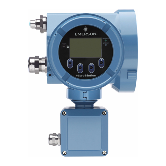
Installation Manual Mounting and sensor wiring MMI-20029768 February 2023 3.6 Rotate the user interface on the transmitter (optional) The user interface on the transmitter electronics module can be rotated 90°, 180°, or 270° from the original position. Figure 3-17: Display components A. -
Page 26: Rotate The Sensor Wiring Junction Box On A Remote-Mount Transmitter (Optional)
3. Gently set the junction box into its new position, confirming that the position is locked. 4. Replace the clamp in its original position and tighten the cap screw. Torque to 28 in lbf (3.16 N m) to 30 in lbf (3.39 N m). Micro Motion 5700 Ethernet Transmitters... - Page 27 Installation Manual Mounting and sensor wiring MMI-20029768 February 2023 Figure 3-20: Re-attach the clamp Installation Manual...
- Page 28 Mounting and sensor wiring Installation Manual February 2023 MMI-20029768 Micro Motion 5700 Ethernet Transmitters...
-
Page 29: Wiring The Channels
Installation Manual Wiring the channels MMI-20029768 February 2023 4 Wiring the channels 4.1 Available channels Signal Channel A Channel B Channel C Channel EtherNet/IP EtherNet/IP mA output options The same protocol must be ordered on both Channel A and B. ProLink III and the Integrated ™... - Page 30 This resistor is normally built into the signal device (d). This resistor is not used for HART communications. D. Signal device Figure 4-2: Externally-powered mA Output wiring A. mA Output B. Channel C. 5–30 VDC (maximum) D. See Figure 4-3 E. Signal device Micro Motion 5700 Ethernet Transmitters...
- Page 31 Installation Manual Wiring the channels MMI-20029768 February 2023 Figure 4-3: Externally-powered mA Output: maximum loop resistance 1100 1000 15.0 22.5 30.0 A. Maximum resistance (Ω) B. External supply voltage (V) 4.2.3 Wire the Frequency Output Wire the Frequency Output in explosion-proof, nonincendive, or nonhazardous installations.
- Page 32 Wire the Discrete Output in explosion-proof, nonincendive, or nonhazardous installations. Prerequisites WARNING Meter installation and wiring should be performed only by suitably-trained personnel using the appropriate government and corporate safety standards. Procedure Wire to the appropriate output terminal and pins. Micro Motion 5700 Ethernet Transmitters...
- Page 33 Installation Manual Wiring the channels MMI-20029768 February 2023 Figure 4-7: Internally-powered DO wiring A. Discrete Output B. Channel C. See Figure 4-8 D. Counter Figure 4-8: Internally-powered DO: output amplitude versus load resistance [24 VDC (Nom) open circuit] 1500 2250 3000 A.
- Page 34 Minimum negative threshold is 0.6 VDC. 4.2.6 Wire the I/O channel using an M12-terminated cable (optional) Use this procedure if you are using an M12-terminated cable to wire the I/O channel. Prerequisites Obtain an A-coded M12-terminated cable. Micro Motion 5700 Ethernet Transmitters...
-
Page 35: Wire The Ethernet Channels
Installation Manual Wiring the channels MMI-20029768 February 2023 Procedure 1. Attach the M12-terminated cable to the configuration I/O connector on the 5700 transmitter. Figure 4-12: M12-terminated cables to the configuration I/O 2. Attach the other cable end using the pinouts described in the following table. Table 4-1: M12 configuration I/O pinouts Wire color Outputs... - Page 36 Functionality is identical for both Channel A and Channel B as the 5700 transmitter contains an internal Ethernet switch. 3. Connect the next transmitter in the network to the unused channel. 4. Anchor the cables to the module backplate using cable ties. Example Micro Motion 5700 Ethernet Transmitters...
- Page 37 Installation Manual Wiring the channels MMI-20029768 February 2023 4.3.2 Wire the Ethernet I/O using M12-terminated cables (optional) Prerequisites Obtain two D-coded M12-terminated Ethernet cables. Procedure 1. Attach both M12-terminated Ethernet cables to the Ethernet I/O connectors on the 5700 transmitter. See Figure 4-13.
- Page 38 Wiring the channels Installation Manual February 2023 MMI-20029768 Micro Motion 5700 Ethernet Transmitters...
-
Page 39: Power Supply Wiring
Installation Manual Power supply wiring MMI-20029768 February 2023 5 Power supply wiring 5.1 Wiring the power supply You can install a user-supplied switch in the power supply line. Important For compliance with the Low Voltage Directive 2014/35/EU (European installations), verify that the transmitter is located in close proximity to a switch. Procedure 1. -
Page 40: Wire The Power Supply Using An M12-Terminated Cable (Optional)
Outputs on board Signal name identification Pin 1 Brown Terminal 3 VDC + Pin 2 White Terminal 1 Channel B + Pin 3 Blue Terminal 4 VDC - Pin 4 Black Terminal 2 Channel B - Micro Motion 5700 Ethernet Transmitters... -
Page 41: Set Up The Printer
Installation Manual Set up the printer MMI-20029768 February 2023 6 Set up the printer Use this section to set up printing with a 5700 Ethernet transmitter and an Epson TM-T88VI Ethernet printer. For information on configuring the printer, see Micro Motion 5700 with Ethernet Transmitters: Configuration and Use Manual. There are two ways to set up printing: •... - Page 42 Page ProLink III Device Tools → Configuration → Printer and Tickets Web browser Configuration → Printer and Tickets For instructions on how to configure print ticket options, see the Micro Motion 5700 with Ethernet Transmitters: Configuration and Use Manual. Micro Motion 5700 Ethernet Transmitters...
-
Page 43: Set Up The Printer Using The Printer Default Ip Address
Set up the printer MMI-20029768 February 2023 If needed, see Function Check Failed in the Status alerts, causes, and recommendations section of the Micro Motion 5700 with Ethernet Transmitters: Configuration and Use Manual. 6.2 Set up the printer using the printer default IP address Use this procedure to set up printing with a 5700 Ethernet transmitter and an Epson TM-T88VI printer using the printer's default IP address. -
Page 44: Reset The Interface Settings
If during this time another transmitter starts a print, the new print may either be rejected, causing a functional check alert (printer offline), or the print will be inserted in the middle of the configuration/audit log print. Micro Motion 5700 Ethernet Transmitters... - Page 45 Installation Manual Set up the printer MMI-20029768 February 2023 The functional check alert is cleared after a successful print. Installation Manual...
- Page 46 Set up the printer Installation Manual February 2023 MMI-20029768 Micro Motion 5700 Ethernet Transmitters...
-
Page 47: Power Up The Transmitter
Installation Manual Power up the transmitter MMI-20029768 February 2023 7 Power up the transmitter The transmitter must be powered up for all configuration and commissioning tasks or for process measurement. Procedure WARNING If the transmitter is in a hazardous area, do not remove the housing cover while the transmitter is powered up. - Page 48 Power up the transmitter Installation Manual February 2023 MMI-20029768 Micro Motion 5700 Ethernet Transmitters...
-
Page 49: Chapter 8 Guided Setup
Installation Manual Guided setup MMI-20029768 February 2023 8 Guided setup At initial startup of the transmitter, the guided configuration screen appears on the transmitter display. This tool guides you through basic configuration of the transmitter. The guided setup allows you to upload configuration files, set the transmitter display options, configure channels, and review sensor calibration data. - Page 50 Guided setup Installation Manual February 2023 MMI-20029768 Micro Motion 5700 Ethernet Transmitters...
-
Page 51: Using The Display Controls
Installation Manual Using the display controls MMI-20029768 February 2023 9 Using the display controls The transmitter display interface includes a display (LCD panel) and four optical switches – left, up, down, and right arrow keys – used to access the display menus and navigate the display screens. - Page 52 Using the display controls Installation Manual February 2023 MMI-20029768 Figure 9-2: Example 1: Active arrow indicators on the transmitter display Figure 9-3: Example 2: Active arrow indicators on the transmitter display Micro Motion 5700 Ethernet Transmitters...
-
Page 53: Available Service Port Connection
Installation Manual Available service port connection MMI-20029768 February 2023 10 Available service port connection Use the service port connection to download or upload data from/to the transmitter. To access the service port, you can use commonly-available USB hardware, such as a USB drive, or USB cable. - Page 54 Available service port connection Installation Manual February 2023 MMI-20029768 Micro Motion 5700 Ethernet Transmitters...
-
Page 55: Appendix A Wire The 5700 To The 3100 Relays
Installation Manual Wire the 5700 to the 3100 relays MMI-20029768 February 2023 A Wire the 5700 to the 3100 relays Use this procedure to wire the Discrete Output on the 5700 Ethernet transmitter to the 3100 transmitter relays for single-stage batch control. Prerequisites •... - Page 56 © 2023 Micro Motion, Inc. All rights reserved. The Emerson logo is a trademark and service mark of Emerson Electric Co. Micro Motion, ELITE, ProLink, MVD and MVD Direct Connect marks are marks of one of the Emerson Automation Solutions family of companies. All...
Need help?
Do you have a question about the Micro Motion 5700 and is the answer not in the manual?
Questions and answers