Table of Contents
Advertisement
Quick Links
THREE-PHASE
HYBRID INVERTER
INSTALLER MANUAL
SUNSYNK 8K-SG04LP3 / SUNSYNK 10K-SG04LP3/
SUNSYNK 12K-SG04LP3
Global Tech China Ltd, 3 Floor, Wai Yip Industrial Building.
171 Wai Yip Street, Kwun Tong, Kowloon, Hong Kong.
Tel: +852 2884 4318 Fax: +8522884 4816
www.sunsynk.com / sales@globaltech-china.com
v.14 (05/03/22)
Advertisement
Table of Contents

Related Manuals for SunSynk 8K-SG04LP3


Summary of Contents for SunSynk 8K-SG04LP3
- Page 1 THREE-PHASE HYBRID INVERTER INSTALLER MANUAL SUNSYNK 8K-SG04LP3 / SUNSYNK 10K-SG04LP3/ SUNSYNK 12K-SG04LP3 Global Tech China Ltd, 3 Floor, Wai Yip Industrial Building. 171 Wai Yip Street, Kwun Tong, Kowloon, Hong Kong. Tel: +852 2884 4318 Fax: +8522884 4816 www.sunsynk.com / sales@globaltech-china.com...
- Page 2 230 Morrison Road, Midvale, WA 6056, Australia +618 9274 4883 Website: www.sunsynk.com.au Email: admin@sunsynk.com.au Manufacturer Sunsynk Limited HK ( Part of Global Tech ) 171 Wai Yip Street Kwun Tong Kowloon Tel: +852 2884 4318 Fax: +852 2884 4816 Website: http://www.sunsynk.com E-mail: support@sunsynk.com...
- Page 3 All information in this User Guide is based on the latest product information available at the time of printing approval. Sunsynk reserves the right to make changes at any time without notice and without incurring any obligation.
-
Page 4: Table Of Contents
Table of Contents 1. SAFETY ......................6 1.1. General Safety ......................6 1.2. Symbols ........................6 1.3. Safety Instructions .....................7 1.4. Disposal Remarks ......................7 2. PRODUCT INTRODUCTION ................8 2.1. System Overview ......................8 2.2. Product Size .......................9 2.3. Features ........................10 2.4. Basic System Architecture ..................11 3. - Page 5 5.9. Factory Reset and Lock Code ................40 5.10. Battery Setup Page ....................41 5.11. Generator & Battery Page ..................42 5.12. Battery Discharge Page ..................45 5.13. Setting Up a Lithium Battery ..................47 5.13.1. Reactive Power Setting (QV) ................51 5.13.2. Active Power Setting (QV) .................51 5.14.
-
Page 6: Safety
1. SAFETY 1.1. General Safety This device should only be used in accordance o instructions within this manual and in ƒ compliance with local, regional and national laws and regulations. Only allow this device to be installed, operated, maintained, repaired by other persons who have also read and understood this manual. -
Page 7: Safety Instructions
1.3. Safety Instructions HIGH LIFE RISK DUE TO FIRE OR ELECTROCUTION. The Sunsynk Single-Phase Hybrid Inverter can only be installed by a qualified li- censed electrical contractor. This is not a DIY product. Be sure to read this manual thoroughly before installation. -
Page 8: Product Introduction
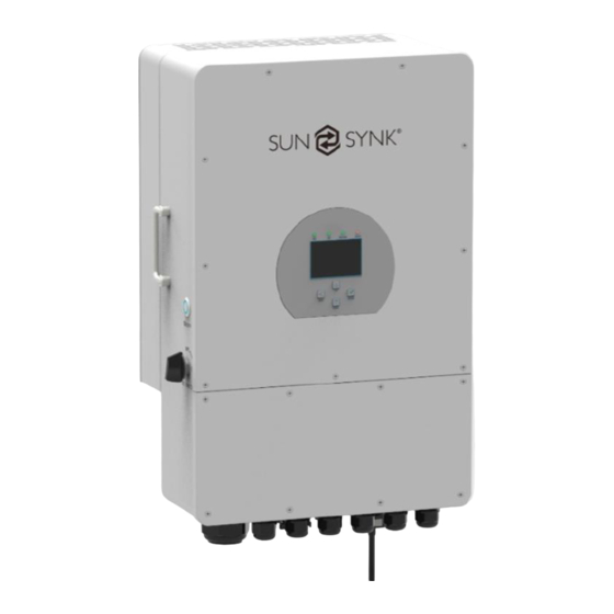
2. PRODUCT INTRODUCTION The Sunsynk Three-Phase Hybrid Inverter is a highly efficient power management tool that al- lows the user to hit those ‘parity’ targets by managing power-flow from multiple sources such as solar, mains power (grid) and generators, and then effectively storing and releasing power as and when utilities require. -
Page 9: Product Size
1. Inverter Indicators 7. Meter-485 port 13. Grid 2. LCD Display 8. Battery input connectors 14. Load 3. Function Buttons 9. Function Port 15. Generator input 4. Power on/off button 10. Modbus Port 16. WiFi Interface 5. DC switch 11. BMS Port 6. -
Page 10: Features
2.3. Features INTERACTIVE ƒ Easy and simple to understand LCD display; ƒ Supporting Wi-Fi or GSM monitoring; ƒ Visual power flow screen; ƒ Built-in 2 strings for 1 MPP tracker and 1 string for 1 MPP tracker; ƒ Smart settable 3-stage MPPT charging for optimised battery performance; ƒ... -
Page 11: Basic System Architecture
2.4. Basic System Architecture The following diagram explains the basic application and architecture of this 3-Phase Inverter. ƒ It also includes following devices to have a Complete running system. ƒ Generator or Utlity ƒ PV modules ƒ Batteries ƒ Normal and smart loads ƒ... -
Page 12: Technical Specifications
3. TECHNICAL SPECIFICATIONS Model SUNSYNK-8K-SG04LP3 Product Type Hybrid Inverter Enclosure IP65 Ambient Temperature -45ºC ~ 60ºC (>45ºC derating) Protection Level Class I Max. Efficiency 97.60% Compatible Batteries Lithium-ion / Lead-acid Charge Mode Battery Voltage 48Vd.c (40Vd.c ~ 60Vd.c) Battery Current 190Ad.c (max.) - Page 13 Model SUNSYNK-10K-SG04LP3 Product Type Hybrid Inverter Enclosure IP65 Ambient Temperature -45ºC ~ 60ºC (>45ºC derating) Protection Level Class I Max. Efficiency 97.60% Compatible Batteries Lithium-ion / Lead-acid Charge Mode Battery Voltage 48Vd.c (40Vd.c ~ 60Vd.c) Battery Current 210Ad.c (max.) AC Input Voltage 3L/N/PE 220/380Va.c, 400Va.c...
- Page 14 Model SUNSYNK-12K-SG04LP3 Product Type Hybrid Inverter Enclosure IP65 Ambient Temperature -45ºC ~ 60ºC (>45ºC derating) Protection Level Class I Max. Efficiency 97.60% Compatible Batteries Lithium-ion / Lead-acid Charge Mode Battery Voltage 48Vd.c (40Vd.c ~ 60Vd.c) Battery Current 240Ad.c (max.) AC Input Voltage 3L/N/PE 220/380Va.c, 400Va.c...
-
Page 15: Installation
4. INSTALLATION 4.1. Parts List Check if you received all the items listed below. Ensure that nothing is damaged in the package. Hybrid Inverter | Installer Manual Page | 15... -
Page 16: Selecting The Mounting Area
4.2. Selecting the Mounting Area For proper heat dissipation, allow a clearance of approximately 500mm to the side, 500mm above and below the unit, and 1000mm to the front of the unit. DO NOT install the inverter in the following areas: ƒ... -
Page 17: Mounting The Inverter
ALSO CONSIDER: ƒ Installing the indoor unit, outdoor unit, power supply cable, transmission cable, and remote control cable at least 1 metre away from any television or radio receiver. This will prevent TV reception interference or radio noise. This will prevent radio signal interference from external units that might interfere with the Wi-Fi or GSM monitoring. - Page 18 Choose the recommend drill head (as shown in below pic) to drill 4 holes on the wall, 52-60mm deep. 1. Use a proper hammer to fit the expansion bolt into the holes. 2. Carry the inverter and holding it, make sure the hanger aim at the expansion bolt,fix the inverter on the wall.
-
Page 19: Battery Connection
4.4. Battery Connection For safe operation and compliance, an individual DC overcurrent protector or disconnection device is required for the connection of the battery and the inverter. Users are recommended to utilise a suitable fuse and DC isolator (see next page). In some applications, switching devices may not be required, but overcurrent protectors must be used. -
Page 20: Function Ports Definition
4.4.1. Function Ports Definition Dry contact Page | 20 Hybrid Inverter | Installer Manual... -
Page 21: Temperature Sensor Connection For Lead-Acid Battery
4.4.2. Temperature Sensor Connection for Lead-Acid Battery Hybrid Inverter | Installer Manual Page | 21... -
Page 22: Connecting The Ac And Backup Load Connection
Without a remote temperature sensor, lead-acid batteries may undercharge or overcharge de- pending on the ambient temperature of the installation environment. This may result in a fire hazard. Depending on the battery type, the inverter should be capable of controlling the batteries BMS. - Page 23 Please follow the steps below to implement GRID, LOAD, and GEN port connections: 1. Before making GRID, LOAD, and GEN port connections, make sure to turn off the AC Be- fore making GRID, LOAD, and GEN port connections, make sure to turn off the AC breaker or disconnector first.
- Page 24 Appliances such as air conditioners require 2-3 minutes to re-start as they need enough time to balance refrigerant gas inside the circuit. If a power shortage oc- curs and recovery is made in a short time, it will cause damage to your connected appliances.
-
Page 25: Connecting The Ct Coil
4.6. Connecting the CT Coil When the inverter is in the off-grid state, the N line needs to be connected to the earth. Hybrid Inverter | Installer Manual Page | 25... -
Page 26: System Connection For The Chnt Meter
4.6.1. System Connection for the CHNT Meter 4.6.2. System Connection for the Eastron Meter Page | 26 Hybrid Inverter | Installer Manual... -
Page 27: Earth Connection (Mandatory)
Since the inverter is a true hybrid then the bond must only be made when the inverter is oper- ating in Islanding Mode. To accommodate this, Sunsynk provides an AC output, which is con- nected to the A/T/S connections whenever the inverter is running on Island Mode. Therefore, you can simply connect the coil of an AC relay to the ATS 240 connections. -
Page 28: Pv Connection
The grid power may still be present, but the inverter is not draining power from it since the unit is working in ‘Island Mode’. You can verify if there is a voltage when the inverter is disconnected from the grid by using a simple multimeter. -
Page 29: Pv Module Wiring
Inverter Model 10kW 12kW PV Input Voltage 450V (140V~1000V) PV Array MPPT Voltage Range 140V~800V No. of MPP Trackers No. of Strings per MPP Tracker 4.8.2. PV Module Wiring 1. Switch the Grid Supply Main Switch (AC) OFF. 2. Switch the DC isolator OFF. 3. - Page 30 1. Strip 7mm of the plastic coating off the DC wire and disassemble the connector cap nut. 2. Crimp metal terminals with crimping pliers. 3. Insert the contact pin into the connector housing until it locks into place. Then screw the cap nut onto the connector housing.
-
Page 31: System Wiring For Inverter
4.9. System Wiring for Inverter The following diagram is an example for an application where the neutral connects with the protective earth (PE) at the switchboard. For countries such as Australia, New Zealand, South Africa, etc., please follow local wiring regulations! Hybrid Inverter | Installer Manual Page | 31... -
Page 32: Wiring Diagram
4.10. Wiring Diagram Page | 32 Hybrid Inverter | Installer Manual... -
Page 33: Typical Application Diagram Of Diesel Generator
4.11. Typical Application Diagram of Diesel Generator Hybrid Inverter | Installer Manual Page | 33... -
Page 34: Operation
5. OPERATION 5.1. Display LED indicator Meaning Green LED solid light PV connection normal Green LED solid light Grid connection normal Normal Green LED solid light Inverter functioning normally Alarm Red LED solid light Fault Function Key Description To exit the previous mode Increase the value of a setting Down Decrease the value of a setting... -
Page 35: Switching On/Off
5.2. Switching ON/OFF Once the inverter has been correctly installed and the batteries have been connected, press the ON/OFF button (located on the left side of the case) to activate the system. When the system is connected without a battery but connected with either PV or grid and the ON/OFF button is switched off, the LCD will still illuminate (display will show off). -
Page 36: Status Page
5.4. Status Page To access the Status page, click on the BATTERY or AC LOAD dial on the Home page. What this page displays: ƒ Total solar power produced. ƒ MPPT 1 power/voltage/current. ƒ MPPT 2 power/voltage/current. ƒ Grid power. ƒ... -
Page 37: System Flow Page
5.5. System Flow Page Access by clicking on the bar chart on the Home Page. What this page displays: ƒ The system flow. ƒ MPPTs power. ƒ Battery status. ƒ Power distribution to load or grid. To better understand the functioning of your system, take a look at the figure bellow: 1. -
Page 38: Setup Page
5.6. Setup Page To access the Settings, click on the gear icon on the right top of the navigation menu. What this page displays: ƒ Serial number. ƒ Software version. ƒ Time, Date, and MCU. What you can do from this page: ƒ... -
Page 39: Set Company Name / Beeper / Auto Dim
5.8. Set Company Name / Beeper / Auto dim To set company name click on the BASIC icon and then on ‘Display’. What this page displays: ƒ Beeper status (ON/OFF). ƒ Installers names. What you can do from this page: ƒ... -
Page 40: Factory Reset And Lock Code
5.9. Factory Reset and Lock Code To access the Settings, click on the gear icon on the right top of the navigation menu. What this page displays: ƒ Reset status. ƒ Whether the ‘lock code’ is used or not. What you can do from this page: ƒ... -
Page 41: Battery Setup Page
5.10. Battery Setup Page To configure battery settings, click on the BATTERY icon and then on ‘Batt type’. What this page displays: ƒ Battery capacity in (Ah) – For non-BMS-batteries the range allowed is 0-2000Ah, while for lithium-ion the inverter will user the capacity value of the BMS. ƒ... -
Page 42: Generator & Battery Page
5.11. Generator & Battery Page To configure battery charging settings, click on the BATTERY icon and then on ‘Batt Charge’. What this page displays: ƒ Generator start voltage/SOC %. ƒ Grid power start voltage/SOC %. ƒ Float V is the voltage at which a battery is maintained after being fully charged. ƒ... - Page 43 The current on thee contacts is limited to approximately, 1Amp 12V. Below is a simple reference circuit of an auto start system that can autostart generators on a boat. (Sunsynk will be releasing a new OS E406 ( Auto-Start ) for better generator control). Hybrid Inverter | Installer Manual...
- Page 44 Page | 44 Hybrid Inverter | Installer Manual...
-
Page 45: Battery Discharge Page
Activating Shutdown causes the inverter to enter standby-mode. It does not com- pletely shut down the inverter. Total shutdown occurs at voltages below 19V. The voltage displayed on the Sunsynk Parity Inverter will vary depending on whether the inverter is charging or discharging the batteries. - Page 46 ƒ Completely Discharged 47.50V Setting the cut-off higher is better for the batteries. The batteries recommended for use with the Sunsynk systems are AGM Lead Acid or Lithium Battery Banks. (‘AGM’ means Absorbed Glass Matt construction that allows the electrolyte to be suspended new the plate’s active material.
-
Page 47: Setting Up A Lithium Battery
5.13. Setting Up a Lithium Battery To set up a lithium-ion battery, click on the BATTERY icon and visit the ‘Batt Type’ column. What this page displays: ƒ This information will only display if the ‘Lithium’ option is selected under ‘Batt Type’. ƒ... - Page 48 2. Check that the data cable is plugged into the correct sockets. Usually, RS485 is employed, but some battery manufacturers use others.. With some types of lithium battery, the BMS cannot be controlled by the Sunsynk inverter. In this case, treat the battery as a lead-acid type and set the charging and discharging protocol following the battery manufacturer specification.
- Page 49 RS485 Inverter Brand Model Storage Notes or CAN Setup Inverter HUBBLE AM-2 5.5KW SSIF2P15S48100C RS485 SACRED FCIFP48100A RS485 Cut Line 3, 6, 8 SSIFP48100A RS485 UZ ENERGY UZ-EB51.2-100ALL ESS-5120 RS485 ESS-10240 RS485 GenixGreen ESS-BOX2 RS485 ESS-BOX3 RS485 ESS-BOX4 RS485...
- Page 50 RS485 Inverter Brand Model Storage Notes or CAN Setup Inverter RJ45 Pin 1: GND 48NPFC80 RS485 RJ45 Pin 2: RS485_A RJ45 Pin 3: RS485_B RJ45 Pins 4, 5, 6, 7, 8: 48NPFC100 RS485 No Connection Narada Single-phase Hybrid 48NPFC150 RS485 Inverter Comm version is E41E Single-phase Hybrid Inverter Comm...
-
Page 51: Reactive Power Setting (Qv)
When communications between battery and inverter does not exist, do not over- charge your battery bank (current or voltage). Many lithium batteries are limited to 100A, some are lower and some are higher. Ensure that voltage and current speci- fications provided by the battery manufacturer are followed. If you are using lead acid batteries then follow the equation of C x 0.25 which means that the maximum charge or discharge you can apply to a battery is a quarter of the AH rating of the overall battery array. -
Page 52: Program Charge & Discharge Times
5.14. Program Charge & Discharge Times To set ‘Charge’ and ‘Discharge’ times, click on the ‘System Mode’ icon after clicking on the gear icon. What this page displays: ƒ A setting to prevent the inverter exporting power to the grid - ‘Zero Export’. ƒ... - Page 53 Concerning the detailed figures above: 1. Tick this box to do not export power back to the grid (the CT coil will detect power flowing back to the grid and will reduce the power of the inverter only to supply the local load). 2.
- Page 54 Example: This example shows the battery being charged up to 100% by both the Grid and Solar PV from 8 a.m. to 11 a.m. and then being able to supply up to 4kW of battery-power to the ‘essential’ loads from the ‘Load’ Port until the battery SOC drops to 50%. IMPORTANT - When charging the batteries from the Grid or Generator, please ensure you have set the correct correct battery-charging settings on the battery charge as shown in Section 4.10 ‘Battery Setup’...
-
Page 55: Grid Supply Page
5.15. Grid Supply Page On the Settings Menu, click on the GRID icon. Grid Mode Australia A 1/13 Phase Type Grid Level 220V-3P 0/120/240 0/240/120 IT system - neutral is not grounded What this page displays: ƒ Grid Mode; ƒ Grid Level; What you can do from this page: In this menu, you can select the country grid. -
Page 56: Advanced Settings For Paralleling Inverters (Under Development)
5.16. Advanced Settings for Paralleling Inverters (UNDER DEVELOPMENT) To configure multi-inverter settings, click on the ADVANCE icon. Master Slave Slave Page | 56 Hybrid Inverter | Installer Manual... -
Page 57: Solar Power Generated
5.17. Solar Power Generated This page shows the daily, monthly, yearly, and total solar power produced. Access this page by clicking on the ‘Solar/Turbine’ icon on the Home Page. 5.18. Grid Power This page shows the Daily / Monthly / Yearly and total grid power export or consumed. Access this page by clicking on the ‘Solar/Turbine’... -
Page 58: Advanced Settings For Auxiliary Load
5.19. Advanced Settings for Auxiliary Load To configure Auxiliary Load (previously known as “smart load”) settings, click on the AUX LOAD icon. What this page displays: ƒ Use of the Gen (Aux) input or output. What you can do from this page: ƒ... -
Page 59: Advanced Settings For Peak Shaving
5.20. Advanced Settings for Peak Shaving To configure Peak Power Shaving function, click on the AUX LOAD icon.icon. What this page displays: ƒ Generator peak shaving is ON or OFF. ƒ Peak Power Shaving value. What you can do from this page: ƒ... -
Page 60: Fault Codes
5.22. Fault Codes To check the fault codes click on the FAULT CODES icon on the settings menu. 2022-01-26 12:45 _VoltLow_Fault 2022-01-24 11:00 _VoltLow_Fault 2022-01-07 18:19 2022-01-08 01:58 2021-11-09 13:22 _VoltLow_Fault 2021-11-03 17:48 _VoltLow_Fault 2021-10-27 16:31 2021-10-20 19:17 If any of the fault messages listed in the following table appear on your inverter and the fault has not been removed after re-starting, please contact your local vendor or service centre. - Page 61 Description Solutions Inverter work mode changed Working Mode Change 1. Reset the inverter. 2. Seek help from Sunsynk. AC Slide over current fault. AC over current fault or 1. Check if the backup load power is within the hardware range of the inverter.
- Page 62 Error Code Description Solutions Battery low voltage 1. Check if the battery voltage is too low. 2. If the battery voltage is too low use the PV or grid to charge the battery. DC bus bar voltage is 3. Check the battery BMS too low Important: Especially with Lithium batteries, ensure...
- Page 63 Chapter 3 ‘Technical Specifications’. If you need further help please refer to the Sunsynk website where you will find training videos and frequently asked questions www.sunsynk.com. Hybrid Inverter | Installer Manual...
-
Page 64: Operation Modes
5.23. Operation Modes 5.23.1. MODE I: Basic 5.23.2. MODE II: With Generator Page | 64 Hybrid Inverter | Installer Manual... -
Page 65: Mode Iii: With Smart-Load
5.23.3. MODE III: With Smart-Load 5.23.4. MODE IV: AC Couple Hybrid Inverter | Installer Manual Page | 65... -
Page 66: Commissioning
6. COMMISSIONING 6.1. Start-Up / Shutdown Procedure The inverter must be installed by a qualified / licensed electrical engineer in accordance to the countries wiring regulations. Before switching on, the installation engineer must have completed the Earth Bond, RCD and earth leakage tests, checked that the solar panel Voc voltage does not exceed 480V and checked the battery voltage. -
Page 67: Information For Commissioning The Inverter
6.2. Information for Commissioning the Inverter After you have successfully powered up the inverter, it must be programmed and set up as per the programming feature above. Check the VOC does Ensure both MPPTs Check each bond on not exceed 480V are balanced the solar panels Measure... -
Page 68: Gdfi Fault
6.3. GDFI Fault Before the inverter connects to the Grid, it will detect the impedance (effective resistance) of the solar PV + to Ground, and the impedance of the solar PV - to ground. If any of the impedance values are less than 33kΩ, the inverter will not connect to the Grid and will report an error F24 on its LCD. - Page 69 2. Be of the type specified in the inverter manufacturer’s instructions or as labelled on the in- verter. We recommend the use of an RCD on all circuits and sub-circuits connected to the Sunsynk Inverter. Below is the specifications for a Residual Current Breaker with Overcurrent Protection (RCBO).
- Page 70 APPENDIX D The Sunsynk inverter can be connected to the internet, but you need to add a data logger to do this. The inverter is compatible with Sunsynk Data-Loggers, which you can obtain from us with your distributor: 1. LAN-Type Data Logger 2.
- Page 71 230 Morrison Road, Midvale, WA 6056, Australia +618 9274 4883 Website: www.sunsynk.com.au Email: admin@sunsynk.com.au Manufacturer Sunsynk Limited HK ( Part of Global Tech ) 171 Wai Yip Street Kwun Tong Kowloon Tel: +852 2884 4318 Fax: +852 2884 4816 Website: http://www.sunsynk.com...
Need help?
Do you have a question about the 8K-SG04LP3 and is the answer not in the manual?
Questions and answers