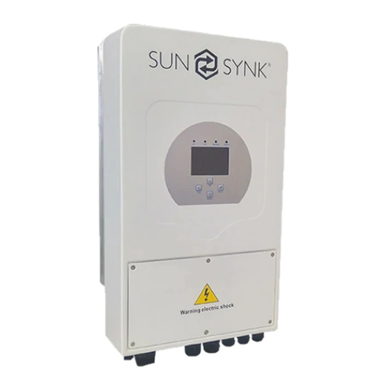
SunSynk Hybrid Parity Installer Manual

SunSynk Hybrid Parity Installer Manual

3.6kw/5.5kw/8.8kw plus parallel version inverters

Advertisement

Hybrid Parity (Super) Inverter
INSTALLER MANUAL
3.6kW/5.5kW/8.8kW PLUS PARALLEL VERSION
SUNSYNK-8K-SG01LP1 SUNSYNK-5K-SG03LP1 SUNSYNK-8K-SG02LP1 SUNSYNK-7.6K-
SG02LP1 SUNSYNK-6K-SG02LP1 SUNSYNK-5K-SG02LP1 SUNSYNK-3.6K-SG02LP1
Global Tech China Ltd, 3 Floor, Wai Yip Industrial Building.171 Wai Yip Street,
Kwun Tong, Kowloon, Hong Kong.
Tel: +852 2884 4318 Fax: +8522884 4816
www.sunsynk.com / sales@globaltech-china.com / www.globaltechhk.com
Version 3.0 (08/06/2020)

Advertisement

Table of Contents
loading
Need help?

Need help?

Do you have a question about the Hybrid Parity and is the answer not in the manual?

Questions and answers

Subscribe to Our Youtube Channel

Summary of Contents for SunSynk Hybrid Parity

  • Page 1 Hybrid Parity (Super) Inverter INSTALLER MANUAL 3.6kW/5.5kW/8.8kW PLUS PARALLEL VERSION SUNSYNK-8K-SG01LP1 SUNSYNK-5K-SG03LP1 SUNSYNK-8K-SG02LP1 SUNSYNK-7.6K- SG02LP1 SUNSYNK-6K-SG02LP1 SUNSYNK-5K-SG02LP1 SUNSYNK-3.6K-SG02LP1 Global Tech China Ltd, 3 Floor, Wai Yip Industrial Building.171 Wai Yip Street, Kwun Tong, Kowloon, Hong Kong. Tel: +852 2884 4318 Fax: +8522884 4816 www.sunsynk.com / sales@globaltech-china.com / www.globaltechhk.com...
  • Page 2 Alarm occurs, the fault code F24 will be displayed on the inverter screen /the LED indicator fault will light All these models fall into two cabinet / PCB types 5.5kW (Small) and 8.8kW (Large): 5kW Type: SUNSYNK-5K-SG02LP1 SUNSYNK-3.6K-SG02LP1 SUNSYNK-6K-SG02LP1 SUNSYNK-5K-SG03LP1 8.8 kW Type...
  • Page 3: Table Of Contents

    Index 1. SAFETY ..............................5 1.1. S ..........................6 YSTEM VERVIEW 2. TECHNICAL SPECIFICATION ......................8 2.1. S ..........................10 YSTEM IAGRAM 3. INSTALLATION ..........................11 ......................11 3.1. S ELECTING THE OUNTING ........................12 3.2. M OUNTING THE NVERTER 3.3. B ........................13 ATTERY ONNECTION 3.3.1 C...
  • Page 4 5. COMMISSIONING ..........................52 5.1. S ..................... 52 TARTUP HUTDOWN ROCEDURE ..................53 5.2. I NFORMATION FOR OMMISSIONING NVERTER ............................54 5.3. GFDI F AULT 6. MAINTENANCE OF THE SYSTEM ...................... 54 APPENDIX A ............................. 55 APPENDIX B ............................. 56 APPENDIX C .............................
  • Page 5: Safety

    1. SAFETY WARNING !!! HIGH LIFE RISK DUE TO FIRE OR ELECTROCUTION. The Sunsynk Parity Hybrid Inverter can only be installed by a qualified licensed electrical contractor. This is not a DIY product.  Be sure to read this manual thoroughly before installation.
  • Page 6: System Overview

    15. Ground connection 16. Data logger The Sunsynk Hybrid Parity Inverter is a highly efficient power management tool that allows the user to hit those ‘parity’ targets by managing power flow from multiple sources such as solar, main electrical grids, and generator, and then effectively storing and releasing electric power as the utilities require.
  • Page 7 Limiting function installed to prevent excess power overflow to grid APPLICATIONS  Marine (vessel power management)  Power shedding (home/office/factory)  UPS (fuel-saving systems)  Remote locations with solar and wind generators  Building sites  Military locations  Telecommunication Website: www.sunsynk.com E-mail: sales@globaltech-china.com...
  • Page 8: Technical Specification

    2. TECHNICAL SPECIFICATION  SUNSYNK-3.6K-SG02LP1 and SUNSYNK-5K-SG03LP1 Model SUNSYNK-3.6K-SG02LP1 SUNSYNK-5K-SG03LP1 Battery Input Data Battery Type Lead-acid or Lithium-ion Battery Voltage Range (V) 40~60V Max. Charging Current (A) 120A Max. Discharging Current (A) 120A Charging Curve 3 Stages/Equalisation External Temperature Sensor...
  • Page 9 Integrated (Except European Type) PV Input Lightning Protection Integrated Anti-islanding Protection Integrated PV String Input Reverse Polarity Integrated Protection Insulation Resistor Detection Integrated Residual Current Monitoring Unit Integrated Output Over Current Protection Integrated Output Shorted Protection Integrated Website: www.sunsynk.com E-mail: sales@globaltech-china.com...
  • Page 10: System Diagram

    -25~60°C, >45°C Derating Cooling Noise (dB) <30 Communication with BMS RS485; CAN Weight (kg) Size (Length x Width x Height) 670 x 420 x 233 mm Protection Degree IP65 Installation Style Wall-mounted Warranty 5 years 2.1. System Diagram Website: www.sunsynk.com E-mail: sales@globaltech-china.com...
  • Page 11: Installation

    Areas where animals may urinate on the unit or ammonia may be generated.  High altitude areas above 4000 meters above sea level.  Environments where precipitation or humidity are above 95%  Areas where the air circulation is too low. ALSO CONSIDER: Website: www.sunsynk.com E-mail: sales@globaltech-china.com...
  • Page 12: Mounting The Inverter

    Be sure to keep other objects and surfaces as shown in the figure to guarantee sufficient heat dissipation and have enough space to remove wires.  For proper air circulation to dissipate heat, allow a clearance of approximately 50cm to the side. Website: www.sunsynk.com E-mail: sales@globaltech-china.com...
  • Page 13: Battery Connection

    DC isolator (see next page). In some applications, switching devices may not be required but overcurrent protectors are still required. A minimum battery cable size of 35mm diameter and 50mm diameter is recommended for the 5.5 kW and 8.8kW inverter, respectively. Website: www.sunsynk.com E-mail: sales@globaltech-china.com...
  • Page 14: Connecting A Lithium Battery

    “Setting Up a Lithium Battery” for setting it up in the inverter: 1. Connect a properly power cable following the battery manufacturer specification and recommend safety devices. 2. Connect communication cable properly following the battery manufacturer specification. 3. Connect to the inverter correctly. Website: www.sunsynk.com E-mail: sales@globaltech-china.com...
  • Page 15: Battery Temperature Connection

    3.3.2. Battery Temperature Connection Without a remote temperature sensor, lead-acid batteries may undercharge or overcharge depending on the ambient temperature of the installation environment. This may result in a fire hazard. Website: www.sunsynk.com E-mail: sales@globaltech-china.com...
  • Page 16: Connecting The Ac

    4.13 “Setting Up a Lithium Battery” and check whether the values are realistic or not. It is important that the charge and discharge limits in that page match the numbers expected for the number of batteries physically connected.  Bottom view of the 3.6kW/5.5kW model  Bottom view of the 8kW model Website: www.sunsynk.com E-mail: sales@globaltech-china.com...
  • Page 17 Be sure to connect corresponding N wires and PE wires to related terminals and ensure the wires are securely connected.  Recommended AC Surge Protector Website: www.sunsynk.com E-mail: sales@globaltech-china.com...
  • Page 18: Installing The Ct Coil

    3.4.1. Installing the CT Coil The CT coil is one of the most important parts of the Sunsynk Parity inverter. This device reduces the power of the inverter to prevent feeding power to the grid. This feature is also known as "Zero Export".
  • Page 19: Earth Connection (Mandatory)

    Ground cable shall be connected to ground plate on grid side this prevents electric shock. if the original protective conductor fails. All neutrals can be linked together to maintain the neutral bond. When Neural Earth bond is required for off-grid, then it has to be removed on grid-tied operation. Website: www.sunsynk.com E-mail: sales@globaltech-china.com...
  • Page 20 Since the inverter is a true hybrid then the bond must only be made when the inverter is operating in Islanding Mode. To accommodate this, Sunsynk provides an AC output, which is connected to the A/T/S connections whenever the inverter is running on Island Mode. Therefore, you can simply connect the coil of an AC relay to the ATS 240 connections.
  • Page 21: Connecting The Pv

    For example, grounded PV modules will cause current leakage to the inverter. Open-circuit voltage (Voc) of PV modules does not exceed max. PV array open-circuit voltage open-circuit voltage (Voc) of PV modules should be higher than min. start voltage. 8.8 kW PV Connection Website: www.sunsynk.com E-mail: sales@globaltech-china.com...
  • Page 22 For example, grounded PV modules will cause current leakage to the inverter. Open-circuit voltage (Voc) of PV modules does not exceed max. PV array open-circuit voltage open-circuit voltage (Voc) of PV modules should be higher than min. start voltage. Website: www.sunsynk.com E-mail: sales@globaltech-china.com...
  • Page 23: Operation

    Function Key Description To exit the previous mode Increase the value of a setting Down Decrease the value of a setting Enter Confirm setting change (If not pressed each time the setting will not be saved) Website: www.sunsynk.com E-mail: sales@globaltech-china.com...
  • Page 24: Switching On/Off

    Total daily power sold to the grid (kWh). Access stats pages.   Total daily power bought from the grid (kWh). Access status page.   Real-time solar power in (kW). Access fault diagnostic page.  Real-time load power in (kW). Website: www.sunsynk.com E-mail: sales@globaltech-china.com...
  • Page 25: Status Page

    DC transformer temperature and AC heatsink temperature (When the temperature reaches 90°C it will show in red and start deteriorating when it reaches 110°C. Next, the inverter will shut down to allow it to cool and reduce its temperature. Website: www.sunsynk.com E-mail: sales@globaltech-china.com...
  • Page 26: System Flow Page

    2. When the batteries reach a specific level (programmable) the battery power is fed into the inverter. 3. The inverter can then supply power to the grid (export or no export), load, and auxiliary or smart load. 4. CT coil controls the export power. Website: www.sunsynk.com E-mail: sales@globaltech-china.com...
  • Page 27: Setup Page

    How to set up (step-by-step): 1. Touch the screen on the variable that you want to change. 2. Change the number up and down using the up and down buttons. 3. Press OK to set the changes. Website: www.sunsynk.com E-mail: sales@globaltech-china.com...
  • Page 28: Set Company Name / Beeper / Auto Dim

    Set a number in the auto dim box to dim the LEO after a number of seconds. How to activate / deactivate the beep: Mark or unmark the beep box and the press OK to configure it as you prefer. Website: www.sunsynk.com E-mail: sales@globaltech-china.com...
  • Page 29: Factory Reset And Lock Code

    TEMPCO settings - Temperature coefficient What you can do from this page: “the error introduced by a change in temperature.  Use battery voltage for all settings (V).  Use battery SOC for all settings (%). Website: www.sunsynk.com E-mail: sales@globaltech-china.com...
  • Page 30: Generator And Battery Page

    Tick Grid Charge to charge the batteries from the grid I/P.  Tick Gen Charge signal to auto-switch a relay box.  Tick Grid Charge signal to auto-switch a relay box. IMPORTANT Do not run this too often since it will damage the battery. Website: www.sunsynk.com E-mail: sales@globaltech-china.com...
  • Page 31 The generator can be controlled via a relay, which is a set of dry contacts. The current on these contacts is limited to 1 Amp 12v, approximately. Below is a simple reference circuit that I used to auto-start generators on a boat. Sunsynk will release a new OS E406 with better Gen control.
  • Page 32: Battery Discharge Page

    Shutdown causes the inverter to enter standby mode. It will not completely shut down the inverter. The total shutdown is below 19V. The voltage displayed on the Sunsynk Parity Inverter will vary depending on whether the inverter is charging or discharging the batteries.
  • Page 33: Setting Up A Lithium Battery

    The batteries normally used in the recommended Sunsynk systems are AGM lead acid or lithium battery bank. (‘AGM’ The Absorbed Glass Matt construction allows the electrolyte to be suspended near the plate's active material. In theory, this enhances both the discharge and recharge efficiency.)
  • Page 34 NOTE Some types of lithium battery the BMS cannot be controlled by Sunsynk inverter. In this case, treat the battery as a lead-acid type and set the charging and discharging protocol following the battery manufacturer specification.
  • Page 35 For example, for a 200AH battery array that could be composed of 4×200 power batteries in series has a maximum charge and discharge of only 50A.  Also, ensure the cable is thick enough to support the current and proper fuse following the recommendations of the battery manufacturers. Website: www.sunsynk.com E-mail: sales@globaltech-china.com...
  • Page 36: Program Charge / Discharge Times Page

    100W to force the inverter to always take this amount of power from the grid to minimise nuisance “Reverse Power Detection” tripping of sensitive prepaid electricity meters. 5. This controls the maximum overall power, both to the load and grid ports combined. It is set to low if an over current fault occurs. Website: www.sunsynk.com E-mail: sales@globaltech-china.com...
  • Page 37 It allows small amounts of power to flow from the grid (set as 100W in this case) to prevent any backflow. In this example, the PV generator prioritizes to supply the load first and then to charge the battery secondarily, Website: www.sunsynk.com E-mail: sales@globaltech-china.com...
  • Page 38: Grid Supply Voltage And Frequency - Grid Supply Page

    The power output or input will vary in response to the AC grid voltage. This function is switched off by default. 1. Click Q( V ) for Volt-Var 2. Click VW for Volt-Watt set points, and adjust if needed Website: www.sunsynk.com E-mail: sales@globaltech-china.com...
  • Page 39 Voltage Trip and Ride-Through (L/HVRT) Frequency Trip and Ride-Through (L/HFRT) Website: www.sunsynk.com E-mail: sales@globaltech-china.com...
  • Page 40: Advanced Settings For Paralleling Inverters

    What you can do from this page:  Set the inverter as a master or slave per bus/wire.  Set the phase in which the inverter will be paralleled.  Set the Modbus SN for paralleling. Website: www.sunsynk.com E-mail: sales@globaltech-china.com...
  • Page 41 The Sunsynk parity inverter can be wired standalone or where more power is required it can be connected in parallel either single or 3 phase configuration. The maximum number of inverters that can be paralleled in a single phase utility grid is three (10.8kW, 16.5kW, and 26.4kW for the 3.6kW, 5.5kW, and 8.8 kW model, respectively) and the maximum number that can be paralleled in a three phase utility grid is nine (32.4kW, 49.5kW, and 79.2kW for the 3.6kW, 5.5kW, and 8.8 kW model, respectively).
  • Page 42 If you need further help please refer to the Sunsynk website where you will find training videos and frequently asked questions www.sunsynk.com. From here you can also update the inverter operating...
  • Page 43: Solar Power Generated

    It can damage the inverter and fault F46 will be indicated on the display. 4.17. Solar Power Generated This page shows the daily, monthly, yearly, and total solar power produced. Access this page by clicking on the “Solar/Turbine” icon on the home page. Website: www.sunsynk.com E-mail: sales@globaltech-china.com...
  • Page 44: Grid Power

    What this page displays:  If one or both of the MPPTs are connected to a wind turbine. What you can do from this page:  Select the MPPT to be used as a turbine input. Website: www.sunsynk.com E-mail: sales@globaltech-china.com...
  • Page 45 Also, the hot water tank controlled via smart load can act as a good dump load, but in very windy conditions it may be necessary to shunt the output. Website: www.sunsynk.com E-mail: sales@globaltech-china.com...
  • Page 46: Advanced Settings For Auxiliary Load

    Tick this box if intending to connect a supplementary inverter For Micro inverter Input or micro inverter (Max. 4kW). Tick this box to stop exporting power produced by the Aux Zero Export Load. Gen Peak Shaving Tick this box to use peak power shaving. Website: www.sunsynk.com E-mail: sales@globaltech-china.com...
  • Page 47: Advanced Settings For Peak Power Shaving

    Peak Shaving: It is a technique used to reduce electrical power consumption during periods of maximum demand on the utility grid. Thus, one can save substantial amounts of money due to peaking charges. Website: www.sunsynk.com E-mail: sales@globaltech-china.com...
  • Page 48: Fault Codes

    Solutions Inverter work mode changed Working Mode Change 1. Reset the inverter. 2. Seek help from Sunsynk. AC Slide over current fault. 1. Check if the backup load power is AC over current fault or hardware within the range of the inverter.
  • Page 49 2. If the battery voltage is too low use the PV or grid to charge the battery. DC bus bar voltage is too low 3. Check the battery BMS Important: Especially with Lithium batteries, ensure that the batteries Max. discharge current or power specification Website: www.sunsynk.com E-mail: sales@globaltech-china.com...
  • Page 50 AC_OverCurr_Failure AC_OverFreq_Fault GFCI_Failure AC_UnderFreq_Fault Tz_COM_OC_Fault AC_U_GridCurr_DcHigh_Fault Tz_Ac_OverCurr_Fault AC_V_GridCurr_DcHigh_Fault Tz_Integ_Fault AC_W_GridCurr_DcHigh_Fault Tz_Dc_OverCurr_Fault AC_A_InductCurr_DcHigh_Fault Tz_GFDI_OC_Fault AC_B_InductCurr_DcHigh_Fault Tz_EmergStop_Fault AC_C_InductCurr_DcHigh_Fault Tz_GFCI_OC_Fault DC_VoltHigh_Fault DC_Insulation_Fault DC_VoltLow_Fault DC_Feedback_Fault AC_BackFeed_Fault BusUnbalance_Fault AC_U_GridCurr_High_Fault DC_Insulation_ISO_Fault AC_V_GridCurr_High_Fault DCIOver_M1_Fault AC_W_GridCurr_High_Fault AC_AirSwitch_Fault AC_A_InductCurr_High_Fault AC_MainContactor_Fault AC_B_InductCurr_High_Fault AC_SlaveContactor_Fault ARC_Fault DCIOver_M2_FaulT Heatsink_HighTemp_Fault Website: www.sunsynk.com E-mail: sales@globaltech-china.com...
  • Page 51 Section 2 “Technical Specification”. If you need further help please refer to the Sunsynk website where you will find training videos and frequently asked questions www.sunsynk.com. Website: www.sunsynk.com...
  • Page 52 3. Switch on Battery and battery breaker 4. Switch on the DC (PV Isolator) Shutdown Sequence: 1. Switch off AC 2. Press the start button 3. Switch off the battery and the battery breaker 4. Switch off the DC (PV isolator) Website: www.sunsynk.com E-mail: sales@globaltech-china.com...
  • Page 53 AC Load, in 3 resistor, caps and rectifier Phase the output voltage will increase across phase to 400V Familiar your self with common fault codes Website: www.sunsynk.com E-mail: sales@globaltech-china.com...
  • Page 54 Check if there are no fault codes and Lithium battery communication is correct. Weekly cleaning statement: Suggest micromesh filters as an available option. Micro ants here are a real problem. Website: www.sunsynk.com E-mail: sales@globaltech-china.com...
  • Page 55 Appendix A Website: www.sunsynk.com E-mail: sales@globaltech-china.com...
  • Page 56 Appendix B Inverters sold in Australia will be set to the Default Australian standards Appendix C The Sunsynk inverter is compatible with the SolarMan app, via a Wifi or GSM data logger (See solarman instruction manual). Copy enclosed Appendix D If an external residual current device (RCD) is used, a device of type (A/AC, etc.) should be employed,...
  • Page 57 166a King William Road HYDE PARK SA 5061 +61(0)429 075 444 Website http://www.sunsynk.com Contact leigh_horton@pm.me Manufacturer Sunsynk Limited ( Part of Global Tech ) 171 Wai Yip Street Kwun Tong Kowloon Tel: +852 2884 4318 Fax: +852 2884 4816 Website http://www.sunsynk.com Contact Info@Globaltech-china.com...

Table of Contents

Save PDF