Table of Contents

Related Manuals for SunSynk 8kW


Summary of Contents for SunSynk 8kW
- Page 1 TRAINING MANUAL Global Tech China Ltd, 3 Floor, Wai Yip Industrial Building.171 Wai Yip Street, Kwun Tong, Kowloon, Hong Kong. Tel: +852 2884 4318 Fax: +8522884 4816 www.sunsynk.com / sales@globaltech-china.com / www.globaltechhk.com 10/26/2020...
- Page 2 1.3.3. MULTI-MODE HYBRID INVERTERS ....................... 9 1.3.4. AC COUPLED HYBRID INVERTERS ......................... 9 1.3.5. BI-DIRECTIONAL DRIVER HYBRID INVERTERS ..................... 10 2. SUNSYNK PARITY BI-DIRECTIONAL DRIVER TYPE HYBRID INVERTER ............11 2.1. THE HEART OF SUNSYNK IS A 8.8 ............... 11...
- Page 3 52 - P ....................52 IGURE ARALLELING INVERTERS PAGE 53 – P ...................... 53 IGURE ARALLELING INVERTERS 54 - D ........................... 54 IGURE IP SWITCH 55 - S ..................55 IGURE UNSYNK INVERTERS PARALLELED 56 - S .
- Page 4 1. INTRODUCTION This training manual has been specifically designed around the Sunsynk Super Hybrid Parity Inverter. It has been written to give you a clear understanding of how to install the inverter, however, users are advised to the inverter handbooks for detailed programming.
- Page 5 25 - S ................27 IGURE TATUS AGE AND THE COIL POWER 26 - S ..........................28 IGURE TRINGS 27 - PV ................30 IGURE CONNECTIONS OF THE INVERTER 28 - 3.6 W/5.5 ....................30 IGURE BOTTOM VIEW 29 –...
- Page 6 52 - P ....................52 IGURE ARALLELING INVERTERS PAGE 53 – P ...................... 53 IGURE ARALLELING INVERTERS 54 - D ........................... 54 IGURE IP SWITCH 55 - S ..................55 IGURE UNSYNK INVERTERS PARALLELED 56 - S .
- Page 7 1. INTRODUCTION This training manual has been specifically designed around the Sunsynk Super Hybrid Parity Inverter. It has been written to give you a clear understanding of how to install the inverter, however, users are advised to the inverter handbooks for detailed programming.
- Page 8 Metal-Oxide-Semiconductor Field Effect Transistor (MOSFET) driven inverters Insulated-Gate Bipolar Transistors (IGBTs) driven inverters. Inverters that employ MOSFET technology are traditional high-frequency inverters, and this drive technology is used in most professional inverters. Currently, some inverters use Silicon-Carbide MOSFETs Website: www.sunsynk.com E-mail: sales@globaltech-china.com...
- Page 9 1.3.3. MULTI-MODE HYBRID INVERTERS Multi-mode hybrid inverters tend to be a larger version of the charger inverter, usually 5kW or 8kW. This inverter has a few more features than a charger inverter, and some can even be wired in parallel.
- Page 10 They are fantastic for use as a UPS, there is no limitation on the size of inverter versus the load, and these inverters use IGBT, which makes them much more reliable against surges and back EMF. Website: www.sunsynk.com E-mail: sales@globaltech-china.com...
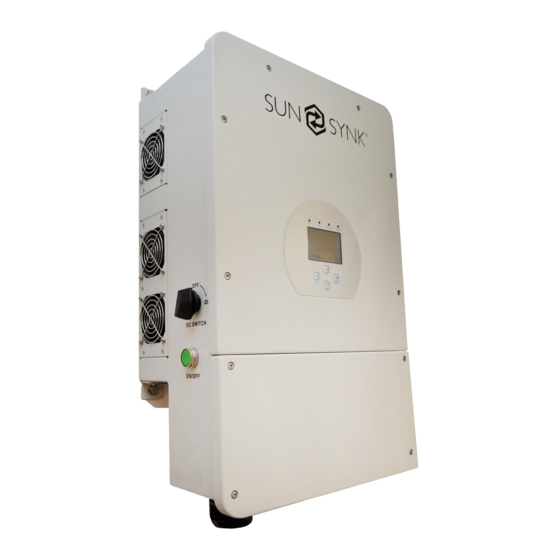
- Page 11 2. SUNSYNK PARITY BI-DIRECTIONAL DRIVER TYPE HYBRID INVERTER 2.1. THE HEART OF SUNSYNK IS A 8.8KW BI-DIRECTIONAL INVERTER The Sunsynk Parity Inverter is a Bi-directional Driver-type Hybrid Inverter. The mains connector on the inverter is both an Input and an Output since it is bidirectional.
- Page 12 Figure 4 - Bottom view of the 3.6kW/5.5kW model Figure 5 - Bottom view of the 8.8kW model Figure 6 - 3.6kW/5.5kW model (small size inverter) Figure 7 - 8.8kW model (large size inverter) Website: www.sunsynk.com E-mail: sales@globaltech-china.com...
- Page 13 If you press the bar chart on the inverter's display, it will come up with a screen showing the flow of power within the inverter. This is very useful and very unique to the Sunsynk inverter. The most important thing about a hybrid inverter is the battery and its ability to store/provide power when needed.
- Page 14 This is selected via the controller, tick ‘Priority to Load’ to divert the solar power to the load; any surplus will charge the battery. If you untick, it will prioritise to charge the battery first, and any surplus will power the load. Website: www.sunsynk.com E-mail: sales@globaltech-china.com...
- Page 15 These outputs 'AUX', 'LOAD' (UPS), and 'GRID' are all controlled via a number of relays. Depending on the control, the setting will depend on what the inverter will do with the power. If you can understand this part of the inverter, you will totally understand how it works. Website: www.sunsynk.com E-mail: sales@globaltech-china.com...
- Page 16 When connecting to the grid, we also use a CT coil, and I will discuss the use of a CT coil further in this manual. Figure 11 - UPS take mode example. Website: www.sunsynk.com E-mail: sales@globaltech-china.com...
- Page 17 Be careful about choosing the location to mount the inverter. Please refer to the User Manual for the best mounting position and location. Figure 12 – Keith Gough at a Sunsynk installation in Port Elizabeth. IMPORTANT: Do not fit the inverter in any area where it is going to be too hot, and the environmental temperature is too hot or humid.
- Page 18 When connecting the inverter, it is not only good practice but maybe also a mandatory requirement to run the AC and the DC cables in separate trunking. Figure 14 - Sunsynk inverter installation - black version. Website: www.sunsynk.com E-mail: sales@globaltech-china.com...
- Page 19 Charging or discharging the batteries with too much current can be dangerous and also damage the battery cells. Once the Sunsynk inverter can deliver a high current level, be careful when selecting the batteries and setting the parameters.
- Page 20 Before making the final DC connection or closing the DC breaker/ disconnection device, ensure that the inverter is wired properly. A reverse polarity connection on the battery will damage the inverter. Figure 16 - Inverters with appropriate battery connections. Website: www.sunsynk.com E-mail: sales@globaltech-china.com...
- Page 21 The battery may look like this: Depending upon the type of battery you are using, it may require either car or RS232 communication. The Sunsynk inverter supports both methods of communication. Website: www.sunsynk.com E-mail: sales@globaltech-china.com...
- Page 22 After installing a lithium battery, check on the communications page by clicking on 'Li BMS' icon to see if the BMS information is visible. If some information is not displayed correctly on the page, as shown in the figures below, there is a communication error. Figure 18 - Displayed information from the Li BMS. Website: www.sunsynk.com E-mail: sales@globaltech-china.com...
- Page 23 Usually, RS 485 is employed, but some battery manufacturers use others. In some types of lithium batteries, the BMS cannot be controlled by Sunsynk inverter. In this case, treat the battery as a lead-acid type and set the charging and discharging protocol as per the battery manufacturer specification.
- Page 24 A 1:2000 Current Transformer Coil (CT-coil) is used to control the power export or the import from the grid. The CT-Coil is one of the most important parts of the Sunsynk Parity inverter. This device reduces the power of the inverter to prevent feeding power to the grid. This feature is also known as ‘Zero Export’.
- Page 25 This cable can be extended up to an extra 10m using a similar cable. 2) Connect the other end of the CT coil into the inverter terminals marked as CT coil. It basically allows the Grid Connection to work as a one-way street. Website: www.sunsynk.com E-mail: sales@globaltech-china.com...
- Page 26 It is important that the grid is connected to follow the arrow into the inverter. The CT coil has two coloured cables: white and black. The white cable is the positive, and the black is negative. Please ensure that they Website: www.sunsynk.com E-mail: sales@globaltech-china.com...
- Page 27 If they are connected backward, a negative value will be shown on the screen. Before connecting to the inverter, please refer to the user manual. Figure 24 - CT coil connections in the inverter. Figure 25 - Status Page and the CT coil power. Website: www.sunsynk.com E-mail: sales@globaltech-china.com...
- Page 28 Depending on the type of inverter you are using, it may allow one or two strings per MPPT. The larger inverters, 8kW and above, normally have two strings per MPPT. Figure 26 - Strings. Before connecting to PV modules, install a separate DC circuit breaker between the inverter and PV modules.
- Page 29 In this circumstance, check if your battery is full and the usage is minimal. Unless you switch the power to the smart load or export the power, it will simply be lost, and you will not be producing any energy from your solar array. Refer to Aux Load output section. Website: www.sunsynk.com E-mail: sales@globaltech-china.com...
- Page 30 Figure 27 shows the PV connection of the 8.8kW inverter while shows the 3.6kW/5.5kW PV connections. For this smaller version, the panels are connected via the MC4 connectors located at the bottom of the inverter, as presented in the diagram.
- Page 31 5. THE DISPLAY The Sunsynk hybrid inverter has the most amazing navigation and information screens of any other inverter in its class. Figure 29 – Amazing interface of the Sunsynk inverter. Once the inverter has been properly installed and the batteries are connected, press the ON/OFF button (located on the left side and underneath the case) to turn on the system.
- Page 32 Total daily power sold to the grid (kWh). Access stats pages. Total daily power bought from the grid (kWh). Access status page. Real-time solar power in (kW). Access fault diagnostic page. Real-time load power in (kW). Website: www.sunsynk.com E-mail: sales@globaltech-china.com...
- Page 33 CT connected to Limit-2, then please reverse the polarity of the home current sensor. Important: See section 3.4 about the CT coil. Inverter Column: Showing inverter total power, frequency, L1, L2, voltage, current, and power. Load Column: Showing total load power, load voltage, and power on L1 and L2. Website: www.sunsynk.com E-mail: sales@globaltech-china.com...
- Page 34 You can clearly see the status of charge and discharge, the battery condition, the exact current flow. This is a very useful screen and it is unique to the Sunsynk product. Figure 32 - Interface with the flow chart.
- Page 35 Lithium or AGM. For this training manual, we are not going to discuss the set up slowly but some specific scenarios (for detailed programming flow, please refer to the user manual). Website: www.sunsynk.com E-mail: sales@globaltech-china.com...
- Page 36 ‘Reverse Power Detection’ which can trip sensitive pre-paid electricity meters. 5) This controls the maximum overall power, both to the load and grid ports combined. It is set to low if an over current fault occurs. Website: www.sunsynk.com E-mail: sales@globaltech-china.com...
- Page 37 In the case of mains failure, the main connection will not have power since it is AC coupled, but your essential loads will still operate. Website: www.sunsynk.com E-mail: sales@globaltech-china.com...
- Page 38 For this application, you need to program the controller to charge the batteries at night and discharge during the daytime. In short [BBGAC]: Basic, Battery, Grid, Advance, Controller. Figure 35 – On-grid with no PV example. Website: www.sunsynk.com E-mail: sales@globaltech-china.com...
- Page 39 Also, be sure you click the Grid on the Battery Set Up, and set your Battery Charging Current according to the type of battery you are using. Generally, if you are using a lithium battery with communication cables to the BMS, it will be automatically set for you. Website: www.sunsynk.com E-mail: sales@globaltech-china.com...
- Page 40 If you are using multi-inverters, then you cannot connect the generator port to the 'GEN/AUX' port. This is because it can cause an imbalance. For example, if you have three inverters on 3-phase and try to use the Website: www.sunsynk.com E-mail: sales@globaltech-china.com...
- Page 41 Some generators can only be run for a certain amount of time, and then they need to cool down. This can be set on the Battery Setup page, shown in the ‘Battery Set Up’ page. Figure 37 - Battery Setup page. Website: www.sunsynk.com E-mail: sales@globaltech-china.com...
- Page 42 2) The generator rating needs to be high enough to supply both the essential and non-essential loads and charge the batteries. Ensure that the generator has a large enough rating because, if it is underpowered, Website: www.sunsynk.com E-mail: sales@globaltech-china.com...
- Page 43 In order to help the generator on a sudden surge current, the Sunsynk inverter steps up the charge current to the battery. At this point it will be providing the full load on switchover.
- Page 44 The unit must be correctly grounded, and the supply line must be equipped with a suitable breaker and Residual Current Devices (RCDs) to protect users. If an external RCD is used, a device of type (A/AC, etc.) should be employed, with a tripping current of 30mA. Website: www.sunsynk.com E-mail: sales@globaltech-china.com...
- Page 45 2) Check type specified in the inverter manufacturer’s instructions or as labelled on the inverter. We recommend the use of an RCD on all circuits and sub-circuits connected to the Sunsynk inverter ie; a Residual Current Breaker with Overcurrent protection (RCBO) 6.4.1.
- Page 46 To use this feature, you will tick ‘Signal Island Mode’, as presented in Figure 42. Figure 42 - Signal island mode. The grid may still be present, but the inverter is not draining power from it as the unit is working in Island Mode. Website: www.sunsynk.com E-mail: sales@globaltech-china.com...
- Page 47 On this page, you can also use the Input for Microinverters and set them with Zero Export. Even if the inverter is Off-Grid/Island mode, you can still use my converters up to a maximum of 4kW extra on the 8.8kW unit.
- Page 48 Also, this technique has another use when working with the generator. You can use a much smaller generator if it is running continuously, and the inverter takes up the peak demand. Figure 45 - Peak shaving. Website: www.sunsynk.com E-mail: sales@globaltech-china.com...
- Page 49 On the Aux Load page, you can select the level when the power shaving starts and the amount of power that the inverter will deliver. Also, do not forget that you need to set the global inverter level on the controller page. Figure 46 - Peak shaving setting. Website: www.sunsynk.com E-mail: sales@globaltech-china.com...
- Page 50 6.7. WIND TURBINES The Sunsynk inverter has been tested with various wind turbines. To connect to a wind turbine, you need to add a connection box, which rectifies the three-phase AC of the wind turbine, adds some limitation, and allows you to connect the turbine to the MPPT directly. This is presented in Figure 47.
- Page 51 IMPORTANT: If you use the wind turbine with the Sunsynk inverter, you must ensure that the turbine matches the specifications of the product. You need to use a Three-Phase p.m. type, with a running voltage of around 200V and a maximum voltage and power of 350V/400V and 5 kW, respectively. Moreover, we strongly recommend using Automatic Self-Breaking Wind Turbines because when are fully charged and the inverter is not exporting any power, the load can drop.
- Page 52 7. PARALLELING INVERTERS Figure 51 - Installation with many inverters. To configure multi-inverter settings, click on the 'Advance' icon. Figure 52 - Paralleling inverters page. Website: www.sunsynk.com E-mail: sales@globaltech-china.com...
- Page 53 5) If the inverters are connected to the communication of the same battery array, the master will control the charges in the other inverters. Website: www.sunsynk.com E-mail: sales@globaltech-china.com...
- Page 54 10) All inverters must be identical, so do not mix up types or software. 11) If you are unsure about the installation, please double-check with Sunsynk and check if you have the latest operating system. It is worth it carrying out an upgrade before you complete the final installation.
- Page 55 After checking and setting all this, you are good to go. As previously mentioned, the most common fault is a communication error between the inverters. Please study the previous Section 7 of this training manual. Figure 55 - Sunsynk inverters paralleled. Website: www.sunsynk.com...
- Page 56 7.2. THREE-PHASE CONFIGURATION The Sunsynk Hybrid Inverter can also be paralleled in a three-phase system with perfect phase rotation. In this case, you need to have three masters, and all the others are slaves. DO NOT forget that each inverter still needs its own unique MODBUS communication number.
- Page 57 This error is an overload on the 'Load' terminal, and it is also quite a common fault. This fault is possibly caused by a heavy surge current from air-conditioners or by a battery issue. Generally, it is caused by a rush current to the load due to many loads switching on at the same time. Website: www.sunsynk.com E-mail: sales@globaltech-china.com...
- Page 58 A high current overload on startup may also cause this cause fault. To clear this fault, you must focus on the battery and battery discharge settings. You need to check the C-rating of the battery. If the battery cannot provide current sufficient for the 8.8kW inverter, it simply crashes out.
- Page 59 F35 - No AC grid This is a simple error that occurs when no AC grid is present, so there is no power coming into the system. You need to find the fault in your AC supply. Website: www.sunsynk.com E-mail: sales@globaltech-china.com...
- Page 60 Generally, this error is a battery problem, possibly a damaged BMS. If you experience an F56 fault, you need to focus on the battery, the battery cables, the battery connections, battery discharging parameters, and the general condition of the battery. 1) Check if battery cables are nice and tight. Website: www.sunsynk.com E-mail: sales@globaltech-china.com...
- Page 61 This error is displayed due to an over-temperature of the IGBT, possibly caused by a blocked fan or ventilation. If this fault occurs and the problem is not solved rapidly, it can damage the inverter. 1) Switch off the inverter and allowed to cool down 2) Clean all ventilation Website: www.sunsynk.com E-mail: sales@globaltech-china.com...
- Page 62 It is important that at least twice a year to clean all the cooling fans and air ducts (for dusty environments, this may need to be carried out more frequently). Figure 59 - Inverter installed in a dusty environment. Website: www.sunsynk.com E-mail: sales@globaltech-china.com...
- Page 63 Global Tech China Ltd, 3 Floor, Wai Yip Industrial Building.171 Wai Yip Street, Kwun Tong, Kowloon, Hong Kong. Tel: +852 2884 4318 Fax: +8522884 4816 www.sunsynk.com / sales@globaltech-china.com / www.globaltechhk.com Website: www.sunsynk.com E-mail: sales@globaltech-china.com...
Need help?
Do you have a question about the 8kW and is the answer not in the manual?
Questions and answers
How does the system work in grid tie mode on signal island mode
The SunSynk 8kW system operates in two modes:
1. Grid-Tie Mode: The inverter synchronizes with the grid and supplies power to connected loads. It can also export excess energy to the grid if allowed.
2. Signal Island Mode: When the inverter is disconnected from the grid (islanding mode), it provides power independently. In this mode, the system activates an AC output connected to the Automatic Transfer Switch (ATS). A relay coil can be connected to the ATS 240V output to manage switching. To enable this mode, the user must select "Signal Island Mode" in the battery charge menu.
This configuration ensures that the system can seamlessly switch between grid-tie and islanded operation as needed.
This answer is automatically generated