
Related Manuals for E.F. Johnson Company Viking VM600


Summary of Contents for E.F. Johnson Company Viking VM600
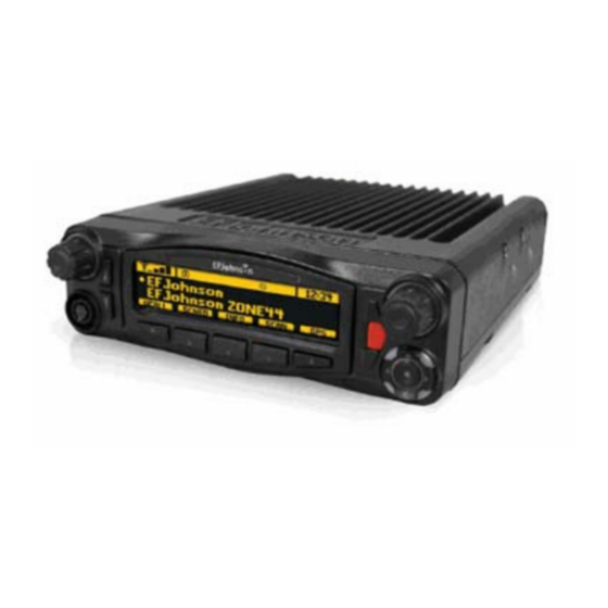
- Page 1 Viking Mobile Radio Operating Manual for the VM600 Radio Project 25 Conventional and Trunking Conventional Analog and Digital ® ® SMARTNET /SmartZone Draft 02 - Sep 1 2015 Part Number 002-0600-03502 September 2015...
- Page 2 © Copyright 2014-2015 by EF Johnson Technologies, Inc. ™ ™ ® The EFJohnson Technologies logo, Armada , Trunked IP25 , and Call Guard are trademarks of EFJohnson Technologies. All other company and/or product names used in this manual are trademarks and/ or registered trademarks of their respective manufacturers.
-
Page 3: Table Of Contents
Viking Mobile Radio Operating Manual September 2015 Contents Radio Overview Capabilities & Features ............1-1 Radio Software and Configuration Programming . - Page 4 Contents External Speaker ............. . 2-17 Internal / External Speaker Programming (Standard Control Head only) .
- Page 5 Contents SMARTNET / SmartZone Mode ..........3-22 P25 Trunking Mode.
- Page 6 Contents Auto / Unmute ..............4-18 Location Services.
- Page 7 Contents DTMF / ANI Signaling ............5-16 Single Tone Encoder .
- Page 8 Contents Receiving a Unit Call (All Types)..........6-7 Telephone Calls .
- Page 9 Contents Encryption Available with Various Channel Types ........7-2 FIPS and Non-FIPS Modes.
- Page 10 Contents Tones & Error Messages Supervisory Tones ............. . 9-1 Error Messages.
- Page 11 List of Figures Viking Mobile Radio (Lightning Control Head) ....... . 1-1 Digital Keypad Microphone .
- Page 12 List of Figures 8.18 Radio Properties Screen: Networking Tab ........8-20 8.19 Radio Connection Window .
- Page 13 List of Tables Standard Control Head Display Symbols........2-4 Lightning Display Operating/Status Mode Symbols.
- Page 14 List of Tables Draft 02 - Sep 1 2015 Viking Mobile Radio Operating Manual...
- Page 15 Safety Requirements Section0 RF Energy Exposure Awareness and Control Information, and Operational Instructions for FCC Occupational Use Requirements Before using your mobile two-way radio, read this important RF energy awareness and control information and operational instructions to ensure compliance with the FCC’s RF exposure guidelines.
- Page 16 Safety Requirements Your EFJohnson Technologies two-way radio has a RF exposure product label. Also, your EFJohnson Technologies user manual, or product manual, or separate safety booklet includes information and operating instructions required to control your RF exposure and to satisfy compliance requirements. Compliance with RF Exposure Standards Your EFJohnson Technologies two-way radio is designed and tested to comply with a number of national and international standards and guidelines (listed below) regarding...
- Page 17 Safety Requirements Transmit only when people outside the vehicle are at least the recommended minimum lateral distance away, as shown in Table 1, from a properly installed according to installation instructions, externally-mounted antenna. Note The following table lists the recommended minimum lateral distance for bystanders in an uncontrolled environment from transmitting types of antennas (i.e., monopoles over a ground plane, or dipoles) at several different ranges of rated radio power for mobile radios installed in a vehicle.
- Page 18 This device complies with Part 15 of the FCC rules. Operation is subject to the condition that this device does not cause harmful interference. In addition, changes or modification to this equipment not expressly approved by the E.F. Johnson Company could void the user’s authority to operate this equipment (FCC Rules, 47CFR Part 15.19).
- Page 19 Safety Requirements television reception, which can be determined by turning the equipment off and on, the user is encouraged to try to correct the interference by one or more of the following measures: • Reorient or relocate the receiving antenna. •...
- Page 20 Safety Requirements Draft 02 - Sep 1 2015 xviii Viking Mobile Radio Operating Manual...
-
Page 21: Radio Overview
E C T I O N Radio Overview Section1 ® This manual is applicable to the Viking Mobile radios. The availability of many of the features is controlled by the model of your radio, factory coding of your radio, installed options, firmware version, and field programming. - Page 22 Radio Overview • Capabilities - 255 zones with 255 channels are supported. A maximum of 2048 channels total, depending on the option selected, may be enabled. ® ® - SMARTNET II , SmartZone Digital and Analog, and P25 Trunking - All supported protocols available simultaneously - Encryption is available depending on the model of your radio: DES-OFB &...
-
Page 23: Radio Software And Configuration Programming
Radio Overview - Dash Mount and Remote Mount Configurations - Standard and Lightning Control Head - Dual Control Heads - Internal or External Speaker - Fixed Control Stations - Siren Option Note The availability of many features is controlled by field programming and by the options ordered. - Page 24 Radio Overview • P25 Phase 2 • P25 Authentication Encryption Options • DES OFB • AES OFB • ARC4 Software Encryption OTAR Options • OTAR P25 Conventional • OTAR P25 Trunking Trunking Options • SMARTNET analog operation • SmartZone analog operation •...
-
Page 25: Licensing
Radio Overview Licensing This radio operates on radio spectrum frequencies assigned and licensed by the Federal Communications Commission (FCC). The FCC can penalize anyone operating an unlicensed radio. It is the radio operator’s responsibility to obtain the necessary license for this radio equipment. -
Page 26: Base Station Unit
Radio Overview When the control is used with a remotely mounted radio, a Junction Box (Part No. 023- 5300-130) must be used. This Junction Box provides various connections for the control and an external speaker, along with connections for programming and rekeying the remote radio. -
Page 27: Controls & Display
E C T I O N Controls & Display Section2 Standard Control Head The standard control head provides the primary controls, display, and speaker for the mobile radio. 2.1.1 Front Panel Controls Figure 2.1 shows the controls for the Viking Mobile radio. Figure 2.1 Front Panel Controls Draft 02 - Sep 1 2015... - Page 28 Controls & Display ON-OFF /Volume - Pressing this control turns power ON and OFF (soft power down can be programmed as in Section 3.1.1.3), and rotating it sets the volume level. Select Switch - This switch can be pressed or rotated. An optional beep can be programmed to sound when it is pressed.
-
Page 29: Display
Controls & Display The user can set an external line by pressing the emergency button. External devices can trigger off of the radio’s external line. If the “Ext Emergency” Option is enabled by programming and the user presses the emergency button, the Aux B line on the accessory connect shall be set to low (0V). -
Page 30: Standard Control Head Display Symbols
Controls & Display Zone Number - Indicates the currently selected zone from 1 up to 255, depending on the options installed. A zone is a collection of channels that can be any combination of the conventional, P25 Trunked, and SMARTNET/SmartZone types. Note The zone/channel numeric display and the zone/channel select bars in all supported protocols and display operating modes can be inhibited by programming. -
Page 31: Lightning Control Head
Controls & Display Standard Control Head Display Symbols (Continued) The current channel is in the enabled scan list (only when scan is on or when in scan edit mode; located in left position) Radio wide scan mode enabled Selected channel is in radio wide scan list (only when radio wide scan is on or when in radio wide scan edit mode) Repeater talk-around enabled Lightning Control Head... -
Page 32: Front Panel Controls
Controls & Display 2.2.1 Front Panel Controls The Lightning Control Head front panel controls are illustrated in Figure 2.5. Figure 2.5 Lightning Control Head Controls Multi-Function On-Off / Volume Select Zone/Channel Display Indicator Switch Switch Microphone Four-Way One-Touch Connection Navigation Pad Programmable Buttons On-Off Volume - This control has two actions: rotation and press. -
Page 33: Lightning Option Buttons
Controls & Display One-Touch Buttons - The control head has 8 one-touch buttons: two on the left of the display, five under the display, and an orange button on the right of the display. These buttons can be programmed with different radio functions. (See the Armada Programming manual for information on programming these button functions.) Figure 2.6 Lightning Option Buttons... -
Page 34: Display
Controls & Display 2.2.2 Display The Lightning Control Head includes a highly readable display. The display is a mono- chrome display with 320 x 80 pixels. The display supports both the Classic Single Line display mode (with the option to combine zone/channel on the display) or enhanced Dual Line functionality. - Page 35 Controls & Display Lightning Control Head Symbols (Continued) The current channel is the priority channel in the enabled scan list (only when scan is on or when in scan edit mode) The current channel is the priority 2 channel in the enabled scan list (only when scan is on or when in scan edit mode) Interconnect mode enabled Unit call mode enabled...
-
Page 36: Mobile Display Modes
Controls & Display Lightning Control Head Symbols (Continued) Indicates that the radio is connected to a wireless access point. 2.2.3 Mobile Display Modes If a Lightning control head is used, the zone and channel indicators can be either turned on or off depending on the display mode programmed. -
Page 37: Classic Mobile Display Without Zone / Channel Indicators
Controls & Display 2.2.3.2 Classic Mobile Display without Zone / Channel Indicators This mode is the same as previous, except with the zone and channel indicators removed, the display text is located in the middle of the screen from both the horizontal and vertical standpoints. -
Page 38: Rear Panel Connectors
Controls & Display Additionally, the display lines can contain up to 16 characters. The icons, status bar, and soft menu labels remain unchanged. Figure 2.11 Lightning Mobile Display without Zone and Channel Indicators Rear Panel Connectors The mobile rear panel connectors are shown in Figure 2.12. These are applicable to both the Standard and Lightning control heads. -
Page 39: Dual Control Configurations
Controls & Display Dual Control Configurations The Viking mobile radio is available in two dual-control configurations, each with different programming and setup requirements: - Dash-mount radio with a remote mount control head - Remote-mount radio with two remote control heads Figure 2.13 Dash-Mount Radio with Remote Control Head Figure 2.14 Remote-Mount Radio with Two Remote Control Heads Note... -
Page 40: Remote Control Head Kit 250-5300-003
Controls & Display The kit does not include the control head removal tool (part number 721-5100-010) which must be ordered separately if required. The remote control cable is also available in 6 foot (part number 597-5357-775-01) and 50 foot (part number 597-5357-775-03) lengths, but these must be ordered separately. 2.4.2 Remote Control Head Kit 250-5300-003 This kit includes the material required to add a remote control head to an existing dash-... -
Page 41: Master / Slave Programming
Controls & Display 2.4.4 Master / Slave Programming In both dual control configurations, either control head can be designated as the Master and the other as the Slave. The Master control head controls the volume of its internal speaker and any external speakers that are connected to the radio's eight-pin accessory connector (see installation manual for connection details). -
Page 42: Dual Control Operation
Controls & Display 2.4.5 Dual Control Operation 2.4.5.1 Programming Dual Remote Control Configurations The Dual Remote configuration requires special programming to accommodate both remote control heads in the mobile radio system. Removal of either control head will affect system performance. 2.4.5.2 Power On / Off The power switching in dual configurations is such that either control head can switch the... -
Page 43: External Speaker
Controls & Display External Speaker An optional 4 ohm, 12 watt external speaker is available from EFJohnson (Part No. 250- 0151-006). This can be used to enhance radio audio or to provide primary audio for a remote-mount radio. Refer to the Viking Mobile Radio Installation Guides for additional installation information. - Page 44 Controls & Display To re-enable the internal speaker, proceed as follows: 1 Power up the mobile radio. 2 Press buttons F2 and F5 at the same time, and release (see Figure 2.15). 3 Rotate the Select knob, until display reads “SPKR ENABL”. 4 After a short time-out period, display will read “CYCLE PWR”.
-
Page 45: General Operation
E C T I O N General Operation Section3 Basic Operation 3.1.1 Turning Power ON and Setting Volume Power is turned ON and OFF by pressing the ON-OFF /Volume knob. The radio goes through a self test when power is turned ON. When that is successfully completed, software version, unit ID, zone, then channel are briefly displayed (except when a conventional analog channel is selected), a tone sounds (if tones are enabled), and the radio is ready for normal operation. -
Page 46: Setting Volume Level
General Operation Note In dual control configurations, the power switch at either control point can be OFF for power to turn OFF. 3.1.1.1 Setting Volume Level The relative volume setting can be determined using a reference tone as follows: • If the key press tones are enabled (see Section 4.6) and if so programmed, a short tone sounds when an option switch is pressed or the Select switch is pressed or rotated. -
Page 47: Persistent Settings
General Operation If the user presses the ON/OFF/Volume knob while soft is in effect, the radio returns to full power up operation. 3.1.2 Persistent Settings Settings retained through power cycle of the Viking mobile radios include. Global Persistent Settings Scan Radio Wide Scan Secure Tones... -
Page 48: Programming Passwords
General Operation The current User password can be changed if the “Change User Password” function is programmed. Selecting this function displays prompts for entering and confirming a new password. Note Standard Control only allows up to a ten digit password while Lightning Control Head allows up to a twelve digit password. -
Page 49: Speaking Into The Microphone
General Operation 3.1.4 Speaking into the Microphone For best results, hold the microphone about 1-2 inches from your mouth and speak at a normal conversational level. Do not shout since it distorts your voice and does not increase range. Note If excessive background noise consistently interferes with communications, Microphone Levels can be adjusted by programming. -
Page 50: Zone / Channel Display And Select
General Operation 3.1.7 Zone / Channel Display and Select The selected zone is shown on the radio display (Figure 3.1). When selected by the Zone/ Channel switch (see Section 3.1.7.1), the select bar will display above the Zone Number. In addition, the alias text identifier for the selected zone will be shown on the display screen. -
Page 51: Zone / Channel Select
General Operation Channel alias can be a combination of zone and channel aliases. With conventional channels, the channel frequency may be displayed instead of the alias if the Display Information function is programmed (see Section 5.8). Figure 3.2 Channel Display Channel Select Indicator Channel Identifier Alias Zone... -
Page 52: Direct Channel Select
General Operation 3.1.7.2 Direct Channel Select The direct Channel Select feature is available if the Channel Select option switch or menu parameter is programmed. This feature allows channels to be directly selected using the Digital Keypad Microphone. Please note that a Digital Keypad Mic is required for Direct entry. -
Page 53: Setting Squelch Control
General Operation • When using the Channel Select knob, wrap-around to the lowest zone/channel occurs after the last channel in the highest programmed zone is displayed and vice versa. For example, if Zone 1/Channel 5 is the highest programmed channel, wrap-around occurs after Zone 1/Channel 16 is displayed if the “Programmed Channels Only On Display”... -
Page 54: Transmit Disable
General Operation • A press-and-hold performs channel delete. To copy a channel: 1 Navigate to the channel and select “channel copy”. 2 Select the destination, first the zone and then the channel. 3 These can be selected by the navigation pad or using direct entry. 4 If the destination channel exists, it is overwritten without warning. -
Page 55: Operation At Extended Range
General Operation 3.1.11 Operation At Extended Range When approaching the limits of radio range, the other party may not be able to hear your transmissions and there may be an increase in background noise when messages are received. You may still be out of range even though you can hear a message. The reason for this is that the signal you are receiving is usually transmitted at a higher power level than the one transmitted by your radio. -
Page 56: Radio Service
General Operation 2 When the bulk of sand and dust is removed, use the brush to clean the interface joint between the buttons and Control Head plastic. 3 Position the vacuum nozzle two inches (or more, as required) from the face of the Control Head. -
Page 57: Single Touch Buttons
General Operation the radio per system and zone. The Single Touch buttons are press and hold buttons preventing a user from sending statuses, messages, and calls by accident. On a Single Touch button press, the radio displays two dual temp messages; the first displays which Single Touch button was pressed along with the press and hold message. -
Page 58: Conventional Call Alert
General Operation To Send a Single Touch Unit Call 1 Press and Hold the Single Touch button assigned to Unit Call. 2 The Unit ID to call is displayed on the top line with the Alias displayed on the bottom line. -
Page 59: Conventional Message
General Operation 2 While sending a Status, the alias of the Status being sent is displayed. 3 Once the Status has been sent operation continues the same as the normal Status with the exception being that only the PTT may be used to resend the Status while the transmission is still active. -
Page 60: P25 Call Alert
General Operation 3 If it is set to Disabled or Response Only; when the Single Touch button is pressed and held the radio will display “Disabled”, “RSPNS ONLY” (Standard Control Head), or “Response Only” (Lightning Control Head) 4 Once the Unit Call has been sent, operation continues as normal for Unit Call. 5 The alias of the radio being called followed by “wait”... -
Page 61: P25 Status
General Operation 3.2.2.7 P25 Status 1 To send a Status, press and hold the Single Touch button assigned to Status. 2 The Status alias programmed to Single Touch is displayed for one second. 3 Either an Ack Received message or a Status Fail message is displayed after the Status has been sent. -
Page 62: Snsz Call Alert
General Operation 3 If it is set to Disabled or Response Only; when the Single Touch button is pressed and held the radio will display “Disabled”, “RSPNS ONLY” (Standard Control Head), or “Response Only” (Lightning Control Head). 4 The alias of the radio being called will be displayed. 5 The operation will now continue the same as a normal Unit Call. -
Page 63: Snsz Status
General Operation 3.2.2.11 SNSZ Status 1 To send a Status, press and hold the Single Touch button assigned to Status. 2 The Status alias programmed to Single Touch is displayed for one second. 3 Either an Ack Received message or a Status Fail message is displayed after the Status has been sent. -
Page 64: Radio Inhibit
General Operation Radio Inhibit The radio can receive inhibit commands over the air or through the side port. When the radio receives an inhibit command the screen goes blank, audio stops, lights turn off, and most of the controls are disabled. The radio is (from the user’s perspective) frozen. Behind the scenes, however, the radio is still running. -
Page 65: Operating Modes
General Operation Operating Modes Each selectable channel can be programmed for the conventional (analog or Project 25 digital), SMARTNET/SmartZone, or Project 25 digital trunking operating mode. For example, Zone 1/Channel 1 could be a conventional channel, Zone 1/Channel 2 a SMARTNET channel, and so on. -
Page 66: Smartnet / Smartzone Mode
General Operation 3.5.2 SMARTNET / SmartZone Mode This is a trunked operating mode in which automatic access is provided to several RF channels. ID codes are used to select what radios are being called and what calls are received. Monitoring is performed automatically and special messages and tones indicate busy and out-of-range conditions. -
Page 67: Systems, Channels, And Zones
General Operation • The P25 control channel data rate is 9600 baud and the digital voice data rate is also 9600 baud. With SmartZone operation, the control channel data rate is 3600 baud (both digital and analog calls) and the narrowband digital voice data rate is 9600 baud. •... -
Page 68: Zones
General Operation 3.5.4.3 Zones A zone is a collection of up to 255 channels of any type. For example, a zone could include 12 conventional channels and four P25 Trunking channels. One use of zones may be to program the channels used for operation in different geographical areas. The maximum number of zones is 255. -
Page 69: Radio Wide Features
E C T I O N Radio Wide Features Section4 Radio wide features are features common to all operating modes. Option Buttons Six option buttons on the front panel (one is located to the left of the display) can be programmed to control a different set of functions for each of the three operating modes. - Page 70 Radio Wide Features The available functions in each mode are shown in Table 4.1 Table 4.1 Programmable Option Button, Soft Button, and Menu Mode Functions X = Available in Mode: Menu Menu Soft Button Display Display Display (Standard (Lightning (Lightning Project 25 Control Control...
-
Page 71: Programmable Option Button, Soft Button, And Menu Mode Functions
Radio Wide Features Table 4.1 Programmable Option Button, Soft Button, and Menu Mode Functions X = Available in Mode: Menu Menu Soft Button Display Display Display (Standard (Lightning (Lightning Project 25 Control Control Control Function Conventional Trunking SMARTNET SmartZone Head) Head) Head) Home 2... -
Page 72: Menu Mode
Radio Wide Features Table 4.1 Programmable Option Button, Soft Button, and Menu Mode Functions X = Available in Mode: Menu Menu Soft Button Display Display Display (Standard (Lightning (Lightning Project 25 Control Control Control Function Conventional Trunking SMARTNET SmartZone Head) Head) Head) Site Lock... -
Page 73: Time-Out Timer
Radio Wide Features For many radio features, <F5> performs as the “Back” button. In these features, to return to the previous screen press <F5>. Some radio features use “Left” and “Right” action buttons. On the Lightning Control Head, these buttons are the left and right arrows on the 4-Way Navigation Pad. On the Standard Control Head <F2>... -
Page 74: Power Output Select
Radio Wide Features Home Zone and Home Channel cannot be set to “Selected” simultaneously. The same applies for Home Zone 2 and Home Channel 2. If Home or Home 2 is set to “Selected,” then Home Channel or Home Channel 2, respectively, will populate with channels 1 to 256. -
Page 75: Ignition Power Down Duration
Radio Wide Features Ignition Power Down Duration The radio can be installed so that the vehicle ignition switch as well as the front panel power switch of the radio control power. This is done by connecting the accessory cable ignition switch input to the vehicle ignition switch. Refer to the Viking Mobile Radio Installation Manual for more information. -
Page 76: Microphone Off-Hook Detect
Radio Wide Features Microphone Off-Hook Detect The microphone hanger can be connected to chassis ground and the radio programmed to detect an off-hook condition (Hangup Box Monitor selected). The following operation then occurs when the microphone is taken off-hook: Conventional Channel Selected - Scanning temporarily halts (if applicable) and the Monitor Mode described in Section 5.2 is enabled. -
Page 77: Scanning
Radio Wide Features In the public address mode, microphone audio is always routed to the PA system, and the radio can be programmed so that receive audio is also routed. When the PA is enabled/ disabled, “EXT PA ON/OFF” is displayed momentarily. The radio can also be programmed to display “EXT PA ON”... -
Page 78: Priority (Standard) Scanning
Radio Wide Features 4.12.1 Priority (Standard) Scanning Priority scanning (also referred to as standard scanning) monitors only channels that are the same type as that currently selected. For example, if a conventional channel is selected, only conventional channels are scanned and likewise for SMARTNET/SmartZone and Project 25 trunking channels. -
Page 79: Scan Hold Time
Radio Wide Features displayed. In addition, (Standard Control Head) or (Lightning Control Head)is displayed along with an R in the left Status position. • To turn radio wide scanning OFF, press the RWS option switch again and “RW SCN OFF” is briefly displayed and (Standard Control Head) or (Lightning Control Head) with R is no longer displayed. -
Page 80: Nuisance Channel Delete
Radio Wide Features 4.12.5 Nuisance Channel Delete With priority scanning, channels can be temporarily deleted from the scan list, for example, if messages become annoying. This feature is not available with radio wide scanning. Channels can also be permanently added or deleted from a scan list as described in the next sections. -
Page 81: Priority Mode Scan Lists
Radio Wide Features 4.13.1 Priority Mode Scan Lists A scan list is simply the channels that are scanned when scanning is enabled. With all operating modes, as many priority scan lists as are required can usually be programmed (up to 255). The only limitation is the available memory. Each list can include up to 255 channels/talkgroups. -
Page 82: Editing A Priority Scan List
Radio Wide Features 4.13.1.3 Editing a Priority Scan List If the Scan Edit option switch is programmed, priority scan lists can be user edited as follows (all operating modes). This option is also selectable via the menu. Changes are permanent (cycling power does not reselect a default condition). Proceed as follows: 1 Select a conventional, SMARTNET/SmartZone/P25 Trunked channel corresponding to the scan list being edited. -
Page 83: Determining Channels In Radio Wide Scan List
Radio Wide Features Each scan list can be selected as User Editable. With this option selected, the user can edit the active scan list only from their radio. The user can also select which scan list is active through a programmed function button or menu function selection. This active scan list is retained through power down. -
Page 84: Over The Air Programming
Radio Wide Features 4.14 Over the Air Programming OTAP is an “Over the Air” programming feature for the subscriber parameter (code plug) files. Using the OTAP feature, parameter files can be updated and changed in the field, eliminating the need to take the radio out of service to perform the updates. Firmware updates cannot be made using this feature. -
Page 85: Over The Internet Programming
Radio Wide Features 4.15 Over the Internet Programming Over the Internet Programming (OTIP) enables you to program Viking mobile radios remotely using IP-based network services. It works with both wired (Ethernet) and wireless (Wi-Fi) networks. Note OTIP is only supported by Viking mobile radios running 8.12.x or later software with the OTIP option enabled. -
Page 86: Concurrent Transfers
Radio Wide Features • A Wi-Fi-connected radio goes out of range. • An Ethernet-connected radio gets its Ethernet cable disconnected suddenly. - When you disconnect a radio’s USB programming cable to replace it with a Wi-Fi dongle—or vice versa—wait at least 3 seconds after you disconnect the first device before you connect the second device. -
Page 87: Gps Data Display
Radio Wide Features It is supported on the Viking Mobile Radio, software version 8.10.x or later. Location service requires an external GPS module connected though the RS232 serial port. The Viking radio supports any receiver with RS232 serial output. The receiver must be configured to transmit the GPGGA and GPRMC NMEA sentences. -
Page 88: Lrrp
Radio Wide Features The “GPS” function allows the user to turn GPS on or off. Pressing the button will toggle the GPS. The display will show “GPS On” or “GPS Off”. Figure 4.2 GPS Icon The GPS icon is only applicable to the LCH. The standard Viking Series control head does not have a GPS icon. -
Page 89: Triggering
Radio Wide Features Table 4.4 Supported LRRP Messages Message Description Triggered-Location-Stop-Request Sent from the LSHS to the radio to tell it to stop doing a previously specified trigger. Triggered-Location-Stop-Answer Sent from the radio to the LSHS to acknowledge the Triggered- Location-Stop-Request. -
Page 90: 4.18 Emergency Alarm Receive Indicator
Radio Wide Features Table 4.5 Supported Triggers Trigger Description Periodic PTT* This trigger happens every time the user presses PTT. This trigger is activated when the user presses the PTT button but the data will usually be sent after the call is over. We do this to avoid delaying the call. -
Page 91: 4.19 Kiosk Mode
Radio Wide Features If multiple Emergency Alarms from different radios are received within the ten second period while the display is still showing, then only the most recent Emergency Alarm ID is shown and the ten-second timer is reset. 4.19 Kiosk Mode A computer may be set up in Kiosk Mode to simplify updating a user’s radio. - Page 92 Radio Wide Features Draft 02 - Sep 1 2015 4-24 Viking Mobile Radio Operating Manual...
-
Page 93: Conventional Mode Features
E C T I O N Conventional Mode Features Section5 Conventional mode features are radio features unique or used only when operating in conventional mode. Monitoring Before Transmitting With conventional operation, you may need to manually monitor the channel before transmitting to make sure that it is not being used by someone else. -
Page 94: Monitor Mode
Conventional Mode Features Busy Indicator - With scanning disabled, note if the multi-function indicator on the front panel is steady green. If it is green, a carrier is being detected, so the channel may be busy. If it is not, the channel is not being used and a call can be transmitted. Monitor Mode - There may be times when the busy indication is displayed even though no one is using the channel. -
Page 95: Busy Channel Lockout
Conventional Mode Features Busy Channel Lockout The Busy Channel Lockout (also called Transmit Disable on Busy) feature automatically disables the transmitter if the channel is busy when the PTT switch is pressed. When the transmitter is disabled by this feature, “BUSY” is displayed, a busy tone sounds, and the transmitter is disabled. -
Page 96: Call Guard Squelch Enable / Disable
Conventional Mode Features 5.4.1 Call Guard Squelch Enable / Disable The Normal/Selective option switch (if programmed) can be used to disable receive Call Guard squelch (Normal/Selective Squelch) on analog channels or group ID code detection on P25 channels. This option is also selectable via the menu. When selective squelch is disabled, “SQ NORMAL”... -
Page 97: Disable Call Guard
Conventional Mode Features 5.4.4 Disable Call Guard The Disable Call Guard feature option lets the radio disregard any CTCSS/DCS or NAC/ Talkgroup information on the current channel. This programmable feature is best described as a monitor mode with no white noise. In analog it is functionally the same as turning the squelch mode to “normal.”... -
Page 98: Penalty Timer
Conventional Mode Features When the Call Guard code is changed using this feature, it remains selected even if other channels are selected. However, if radio power is cycled or a talk-around channel is selected, the normal codes are reselected. When scanning, the selected code also applies to all scanned channels. -
Page 99: Conversation Timer
Conventional Mode Features Conversation Timer A conversation timer can be programmed on conventional systems in addition to the time- out timer (see Section 4.3). This timer limits that total length of a conversation rather than just the length of each transmission as with the time-out timer. The following is more information on this timer. -
Page 100: Emergency Alarm And Call
Conventional Mode Features This feature is available on conventional channels only. Emergency Alarm and Call Emergency Alarms and Calls are separate functions that can be individually enabled or disabled on each analog and P25 conventional system. The Emergency option switch (or menu selection) is required for these functions. -
Page 101: Emergency Call Alert
Conventional Mode Features If silent programmed, none of these indications occur. If “No Receive Activity During Emergency” is programmed, receive audio, the front panel LED, and receive icons are disabled in the receive mode. 3 When the emergency alarm is acknowledged by the dispatcher, “ACK RECVD” is briefly displayed on the Standard Control Head, “ACK Received”... -
Page 102: Emergency Hot Mic
Conventional Mode Features 5.9.3.1 Emergency Hot Mic If Emergency Hot Mic has been enabled for emergency calls for the system, automatic transmitting occurs with microphone audio unmuted without having to manually press the PTT switch. The automatic transmit period is programmed for 10-120 seconds in ten- second intervals. -
Page 103: Emergency Talkgroup
Conventional Mode Features The user has the ability to use two different timers for Emergency mode (Conventional system) - one to enable and one to disable emergency mode, preventing accidental enabling and disabling of emergency mode. With Emergency Press and Hold enabled, emergency mode is enabled when the Button Press/Hold Duration Timer expires. -
Page 104: Transmitting In Scan Mode
Conventional Mode Features status display for the Standard Control Head or is not indicated on the top of the screen for the Lightning Control Head. If required, turn scanning OFF by briefly pressing this switch. If the SCAN option switch is pressed while scanning, Nuisance Channel Delete described in Section 4.12.5 is performed. - Page 105 Conventional Mode Features Note In addition, the priority channel is not scanned if the active channel is an analog channel on the same frequency as the priority channel and is programmed with CTCSS/DCS squelch control. Either a single or dual priority channels can be programmed if desired. With dual priority, a call on the second priority channel is interrupted by a call on the first priority channel but not vice versa.
-
Page 106: Changing The Priority Channel
Conventional Mode Features 5.10.3.1 Changing The Priority Channel If a fixed priority channel is associated with the current scan list, it can be changed to another channel if the Priority option switch, menu function, or soft button function (Lightning Control Head only) is programmed. With dual priority, this changes only the first priority channel. -
Page 107: Standard Conventional Calls
Conventional Mode Features 1 The Talkgroup Lock Feature can be enabled / disabled from a programmable button or menu. The radio must be on a P25 Conventional Channel or else the radio will bad beep. 2 Talkgroup Select The current functionality of Talkgroup Select is (TG Lock Disabled) User is able to direct entry a Talkgroup or select a Talkgroup from a list. -
Page 108: Placing A Standard Conventional Call
Conventional Mode Features 5.11.1 Placing a Standard Conventional Call To place a standard conventional call, proceed as follows: 1 Turn power ON and set the volume as described in Section 3.1.1. Select the channel programmed for the radio you want to call (see Section 3.1.7.1). 2 Monitor the channel automatically or manually as described in Section 5.1. -
Page 109: Single Tone Encoder
Conventional Mode Features When an emergency alarm or call is placed, this ANI signaling is replaced by the Emergency DTMF ID (see Section 5.9). Refer to Section 5.12.5 for information on MDC1200 ANI. 5.12.1 Single Tone Encoder The radio will transmit and send a single tone as programmed. Single tone ANI provides call-in signaling, but does not provide identification of individual units, i.e. -
Page 110: Two Tone Decoder
Conventional Mode Features The third is pressing and holding a button programmed for Two Tone. This will enter the Two Tone List. Again, from this point, scrolling to the desired tone in the list and pressing PTT or the select button will activate and store the Two Tone. Finally, Two Tone can be activated by using Emergency Analog Signaling, ANI Analog Signaling, or RTT Analog Signaling. -
Page 111: Ge Star
Conventional Mode Features Inhibit/Uninhibit Commands - Command to inhibit (disable) and uninhibit (enable) mobile access to the radio system. 5.12.6 GE Star GE Star signaling is implemented for transmit functionality. Two programming modes are available: Standard format (normal ANI for pre- and post- ANI and RTT and emergency). NYSP format (emergency) 5.13 Project 25 Mode Features... -
Page 112: Network Access Code (Nac)
Conventional Mode Features 5.13.3 Network Access Code (NAC) Project 25 conventional channels also use a NAC (Network Access Code) to control which calls are received on a channel. The NAC can be 1-4095, and each transmit and receive channel can be programmed for a different code. Other operation, such as monitoring before transmitting, is similar to that of analog channels. -
Page 113: Efjohnson System Automatic Registration
Conventional Mode Features Both the Entering OOR and Exiting OOR Tones will be disabled to avoid excess tones from fringe areas where the radio is toggling in and out of coverage. Tones are restored on power cycle. 5.13.5 EFJohnson System Automatic Registration When used in a EFJohnson P25 conventional infrastructure radio system, an option on the radio can be programmed to provide additional identifying information to the system upon receipt of a dynamic data registration request. -
Page 114: Changing Talkgroup Assigned To A Channel
Conventional Mode Features 5.13.6.1 Changing Talkgroup Assigned To a Channel If the Talkgroup Select option switch is programmed, the talkgroup assigned to a channel can be changed by the user. The operation can also be selected from the menu as Select TG, or “TGSEL”... -
Page 115: Direct Channel Entry
Conventional Mode Features 4 When a unit ID call is received, three beeps sound every six seconds four times (if tones are enabled), and “CALL RECVD” (Standard Control Head) or “Call Received” (Lightning Control Head) and the alias of the Unit ID are alternately flashed. 5 To respond, select the Unit Call mode by pressing the Unit Call option key. -
Page 116: P25 Conventional Telephone Calls
Conventional Mode Features 5.13.8 P25 Conventional Telephone Calls Telephone calls can be placed and received on P25 conventional channels with a Network Interface Unit (NIU). EFJohnson also supports telephone calls to be placed and received over other vendor’s public telephone. Telephone calls are programmed to operate in one of the following modes: •... -
Page 117: Answering A Telephone Call
Conventional Mode Features 4 Briefly press the PTT switch to send the access code. A dial tone sound should then be heard. Briefly press the PTT switch again to send the digits. Proceed to Step 5 (in next steps): For direct entry using front panel controls or the keypad on the Digital Keypad microphone: 1 Select the conventional channel that is programmed to select the desired access and de- access codes. -
Page 118: Call Alert
Conventional Mode Features 5.13.9 Call Alert The Call Alert™ feature allows pages to be sent and received on P25 conventional channels. The Call Alert Encode and Decode options must be enabled (by programming) to send or receive an alert. Operation is similar to SMARTNET/SmartZone and P25 Trunking channels. -
Page 119: 5.13.10 Call History
Conventional Mode Features Control Head) is displayed six seconds after the PTT switch is pressed. Auto exit then occurs. 5.13.10 Call History If programmed, the Call History feature stores the IDs of the last five radios that have made talkgroup calls, unit calls, or call alerts to the user’s radio. To view the Call History list: 1 Access Call Alert or Unit Call List from the menu. -
Page 120: 5.13.12 Status Messaging
Conventional Mode Features 5.13.12 Status Messaging The status messaging feature allows you to manually or automatically send your current status to your dispatcher on P25 channels. Up to 255 status conditions can be preprogrammed, and they are identified by an alias. If the STATUS option switch is programmed, status conditions are sent as follows: 1 Momentarily press the STATUS option switch, soft button (Lightning Control Head only), or select the option via the menu. -
Page 121: Menu Structure
Conventional Mode Features Keypad programming is selected by pressing the Keypad Programming option switch or by selecting the option from the menu (password entry is not required). The keypad programming mode is indicated by “CHNG ZONE” and a triangle (Standard Control Head) or “Change Zone”... -
Page 122: Zone Password
Conventional Mode Features Press the Select switch to select the displayed parameter. A single beep sounds when the switch is pressed (if that option is enabled). Press the Keypad Programming option switch from one of the main menus to exit keypad programming or from other menus to exit back one level. -
Page 123: Zone Change Parameter
Conventional Mode Features When an attempt is made to select a system or channel parameter in a password protected zone, “PASSWORD” is flashed. The password is always eight digits long and is entered using the same procedure as used for the power-up password described in Section 3.1.3. After the password is entered, system and channel parameters for that zone can be reprogrammed normally. -
Page 124: Channel Parameters
Conventional Mode Features SCAN TIMER - Selects the Scan Hold timer. Rotate the Select switch to decrement/ increment the timer in 0.5-second steps from 0-7.5 or set it to 0 seconds to disabled it. When the desired value is displayed, store it by pressing the Select switch. A single beep sounds when the switch is pressed (if that option is enabled). - Page 125 Conventional Mode Features RX CODE - Sets the receive Call Guard (CTCSS/DCS) code. The currently selected code is initially displayed. If required, rotate and press the Select switch to select the desired code type (CTCSS analog or DCS digital). If an invalid code is entered, a beep sounds, “INVALID”...
-
Page 126: Text Messaging
Conventional Mode Features store it by pressing the Select switch. A single beep sounds when the switch is pressed (if that option is selected). Note The channel spacing is not set with P25 channels because it is always narrow, and the squelch cannot be changed because the setting is critical for proper receiver operation. -
Page 127: Receiving A Text Message
Conventional Mode Features If “Set R to R” is disabled: • A text message can be received from radios on a digital channel with a repeater if PCTextMessage is connected to that repeater (all radios must be dynamically registered to the repeater) •... - Page 128 Conventional Mode Features 2 Use the Select knob to move through the list to the desired message. 3 To view the message text, press the Select knob. Note Text messages are retained only while the radio is powered up. If power is removed, all text message data is lost.
-
Page 129: Smartnet / Smartzone / P25 Trunked Features
E C T I O N SMARTNET / SmartZone / P25 Section6 Trunked Features The features described in this section are radio features unique to these modes of operation. Analog and Digital Operation Either analog or digital operation can be selected for communication on SmartZone traffic channels. -
Page 130: Radio Info Button
SMARTNET / SmartZone / P25 Trunked Features 6.2.1 Radio Info Button Pressing the Radio Info button (if programmed) or selection of the menu parameter allows the user to display the ID programmed for the currently selected protocol. If the radio is on a digital conventional channel, it shows the digital conventional ID. -
Page 131: Receiving A Standard Group Call
SMARTNET / SmartZone / P25 Trunked Features 3 Press the PTT switch and begin talking. An optional talk permit tone may sound to indicate when talking can begin. Other indications that may occur are as follows: - If in the secure mode and your radio is not programmed with the proper encryption key, “KEYFAIL”... -
Page 132: Unit Calls
SMARTNET / SmartZone / P25 Trunked Features Unit Calls Unit calls allow calls to be placed to a specific radio. Either the Enhanced or standard modes may be programmed depending on the capabilities of the radio system. One difference between these call types is that the Enhanced type provides an indication that the called mobile is not on the air and the standard version does not. -
Page 133: Placing A Standard Unit Conversation Call
SMARTNET / SmartZone / P25 Trunked Features microphone, enter the number using the DTMF keypad. To cancel the call, press the Unit Call Option key again. Note If the Unit Call option is programmed to either the F2 or F3 buttons on the Standard Control Head, you must use the F6 button to exit the function. - Page 134 SMARTNET / SmartZone / P25 Trunked Features 3 Press the PTT switch to initiate the call. (Proceed to the bulleted list which follows Item 3 in the next section for events that may occur next.) To make a direct entry from the menu (scroll down to select direct entry), or by using front panel controls or the keypad on the Digital Keypad microphone: 1 Press and hold the Unit Call option key until a tone sounds (approximately one second).
-
Page 135: Receiving A Unit Call (All Types)
SMARTNET / SmartZone / P25 Trunked Features 6.4.3 Receiving a Unit Call (All Types) To receive a Unit Call: 1 When an unit call is received, “CALL RECVD” (Standard Control Head) or “Call Received” (Lightning Control Head) is displayed and the call tone sounds once. The unit ID of the calling mobile is displayed. -
Page 136: Placing A Telephone Call
SMARTNET / SmartZone / P25 Trunked Features 6.5.1 Placing a Telephone Call To recall from a list: 1 With a SMARTNET/SmartZone/P25 channel selected, momentarily press the Phone option switch, soft button (Lightning Control Head only), or select the menu parameter. The alias of the last called telephone number is displayed. -
Page 137: Receiving A Telephone Call
SMARTNET / SmartZone / P25 Trunked Features the PTT switch and dial the number using the keypad on the Digital Keypad microphone. If the selected telephone number is not valid, “INVALID” is displayed and an alert tone sounds. Select a valid number. If the system is busy, “BUSY”... -
Page 138: Answering A Page
SMARTNET / SmartZone / P25 Trunked Features 6.6.1 Answering a Page To answer a Page: 1 When a page is received, five beeps sound and “PAGE RECVD” (Standard Control Head) or “Page Receive” (Lightning Control Head) is displayed. The ID of the radio paging you is stored as the last ID received. - Page 139 SMARTNET / SmartZone / P25 Trunked Features 2 If using the front panel controls, enter the ID of the radio you are calling by rotating the select switch, pressing F3 (Standard Control Head) or right on the Navigation pad (Lightning Control Head) to advance the cursor. The F2 button (Standard Control Head) or left on the Navigation Pad (Lightning Control Head) can be used to move the cursor back to correct an entered number.
-
Page 140: Messaging
SMARTNET / SmartZone / P25 Trunked Features Messaging The messaging feature allows preprogrammed messages to be sent to your dispatcher. Up to 255 messages can be preprogrammed, and they are identified by an alias. Messages are sent as follows: 1 Momentarily press the Message option switch, soft button (Lightning Control Head only), or select the menu parameter. -
Page 141: Sending Status Conditions
SMARTNET / SmartZone / P25 Trunked Features made by pressing the select button or the PTT. Upon sending the Message, the radio will wait until the Message has been sent, and then display the appropriate message for whether it was received successfully or not. If the Message was not sent successfully, the radio will return back to the Message menu to allow the user to try again or try a different Unit ID or Message. -
Page 142: Emergency Alarm And Call
SMARTNET / SmartZone / P25 Trunked Features Emergency Alarm and Call Emergency Alarms and Calls are separate functions that can be individually enabled or disabled on each SMARTNET/SmartZone and P25 Trunking system. The Emergency option switch, soft button (Lightning Control Head only), or menu selection is used for these functions. -
Page 143: Emergency Call Alert
SMARTNET / SmartZone / P25 Trunked Features 2 When the emergency alarm is acknowledged, “ACK RECVD” (Standard Control Head) or “Ack Received” (Lightning Control Head) is briefly displayed and the emergency acknowledge tone (five beeps) sounds. Silent operation may also be programmed in which case no tone sounds and there is no indication that an acknowledgment occurred. -
Page 144: Placing An Emergency Call
SMARTNET / SmartZone / P25 Trunked Features 6.9.3.2 Placing an Emergency Call To place an Emergency Call: 1 If required, select a channel of a system on which Emergency Calls are enabled and press the Emergency option switch, soft button (Lightning Control Head), or select the menu option. -
Page 145: Failsoft Operation
SMARTNET / SmartZone / P25 Trunked Features With the emergency press and hold feature enabled, the emergency button must be pressed and held for the duration of the press and hold timer for emergency mode to be activated. If the button is released before the timer has expired a bad beep tone sounds and emergency mode fails to activate. - Page 146 SMARTNET / SmartZone / P25 Trunked Features • Scanning is turned ON and OFF by the Scan option switch, soft button (Lightning Control Head only), or selecting the menu parameter. Talkgroups (channels) can be programmed so that scanning automatically starts whenever the talkgroup is selected (Autoscan).
-
Page 147: Priority Talkgroup Sampling
SMARTNET / SmartZone / P25 Trunked Features 6.11.1 Priority Talkgroup Sampling One talkgroup in the scan list can be designated a priority talkgroup by programming or it can be the selected talkgroup. When scanning, messages on a non-priority talkgroup are interrupted by messages on the priority talkgroup. -
Page 148: Dynamic Regrouping
SMARTNET / SmartZone / P25 Trunked Features 2 The currently selected list is displayed as “LIST x”, with “x” the currently selected list. To exit without changing the selected list, press the appropriate exit button. 3 To select another list, “PROGRAMMED”, or “NO LIST”, rotate the Select switch. When the desired list is displayed, select it and exit this mode by pressing the appropriate exit button. -
Page 149: 6.13 P25 Radio Unit Monitor
SMARTNET / SmartZone / P25 Trunked Features 6.13 P25 Radio Unit Monitor This feature allows a dispatcher to remotely monitor a radio from the console. This can be especially useful when a radio is lost, stolen, or in cases of emergency. The dispatcher may choose to make the user aware of this monitor or not. -
Page 150: Busy Override
SMARTNET / SmartZone / P25 Trunked Features 6.14.1 Busy Override The busy override feature is enabled at the system level by the system manager and is not a programmable radio feature. It allows a call to be placed even if not all of the sites you are calling have a free traffic channel. -
Page 151: Locking / Unlocking A Site
SMARTNET / SmartZone / P25 Trunked Features To scroll through the other programmed sites, press and hold the SITE SEARCH option switch while “SITE xx” or “RSSI xx” is displayed. If site lock is ON when site search is entered (see following), the radio will be locked on the new site when this function is exited. -
Page 152: Normal P25 And Smartzone Control Channel Hunt
SMARTNET / SmartZone / P25 Trunked Features 1 Assume TG1 is selected. If it is the first time this talkgroup is selected, normal searching for a control channel occurs according to the hunt methods previously described. 2 When another talkgroup is selected, the active valid site for TG1 is stored in memory. 3 The next time TG1 is selected, the following procedure is performed before performing the normal hunt methods previously described. -
Page 153: Radio Information
SMARTNET / SmartZone / P25 Trunked Features The problem with this operation is that every time a different talkgroup is selected, the access permission may be different and a different site may need to be accessed. This could result, in a worst case, in a delay of up to 30 seconds in finding a new site. This could occur if there are no valid sites for the new talkgroup in the dynamic site list. -
Page 154: P25 Trunking System Single Touch
SMARTNET / SmartZone / P25 Trunked Features 6.15 P25 Trunking System Single Touch For the Viking mobile radio, three control heads can use Single Touch. The Standard control head and Lightning control head for the Viking mobile radio operate very similar to the Viking portable radios. -
Page 155: Sending A Message
SMARTNET / SmartZone / P25 Trunked Features 6.16.1 Sending a Message To send Messages from one radio to another, the user must select a Unit ID and a Message. The Unit ID can either be selected from the Unit Call list programmed in Armada, or may be entered by the user. - Page 156 SMARTNET / SmartZone / P25 Trunked Features Draft 02 - Sep 1 2015 6-28 Viking Mobile Radio Operating Manual...
-
Page 157: Secure Communication (Encryption)
E C T I O N Secure Communication (Encryption) Section7 This radio may be equipped to provide secure communication on some or all channels. This feature encrypts the voice so that it can be understood only by someone using a radio equipped with a similar encryption device and encryption codes. -
Page 158: Aes
Secure Communication (Encryption) 7.1.2 An encryption standard called AES (Advanced Encryption Standard) is replacing DES- OFB encryption on digital (P25) channels. It uses a 256-bit encryption key instead of the 64-bit key used with DES. The type of encryption (DES or AES) is determined by the type of encryption key that is loaded (see Section 7.2). -
Page 159: Encryption Keys
Secure Communication (Encryption) Encryption Keys An encryption key is a cryptographic variable that is required by the encryption algorithm to encrypt and decrypt voice or data. To maintain system security, these keys must be protected from disclosure and also periodically replaced or updated. With the AES and DES hardware encryption and ARC4 software encryption used by EFJohnson Technologies radios (see Section 7.1), the same encryption key is used by both the encrypting (sending) and decrypting (receiving) radio. -
Page 160: Pid / Sln Key Management Modes
Secure Communication (Encryption) 7.2.2 PID / SLN Key Management Modes The channels, talkgroups, and other calls that use encryption are linked to a specific Physical ID (PID) when the radio is programmed. For example, Zone 1, channel 1 could be programmed to select the key in PID 1 and Zone 1, channel 2 could select the key in PID 3. -
Page 161: Maintaining Keys In Memory
Secure Communication (Encryption) 7.2.3 Maintaining Keys in Memory The radio may need to be connected to a constant power source to preserve the encryption keys in memory. The programming of the Infinite Key Retention parameter determines if keys are permanently stored in memory or erased soon after power is removed. When Infinite Key Retention is enabled, keys are stored in memory and are not lost when power is removed. -
Page 162: Encryption Icon Operation
Secure Communication (Encryption) 7.2.6 Encryption Icon Operation The encryption icon (Standard Control Head) or (Lightning Control Head) flashes whenever a secure call is received or transmitted. Other operation is as follows: • The icon is always displayed when the radio is in secure mode and receives a clear call on a digital and P25 trunking channel. -
Page 163: Security Settings Override
Secure Communication (Encryption) If the Clear/Secure switch is not programmed, the radio is always in the last known state (usually Clear) and there is no way to change it. For example, if the last known state is Clear and this parameter is not selected, it is never possible to transmit a Secure message on a channel strapped Secure because all that happens is transmitting is disabled, an error tone sounds, and “SEC ONLY”... -
Page 164: Channel With Talkgroup Specified
Secure Communication (Encryption) 7.4.2.2 Channel with Talkgroup Specified If the override security settings feature is enabled, then the override parameters will be used. If the override feature is not enabled, then the talkgroup parameters will be used. If the Any Key option is disabled and a secure talkgroup call is received that uses a different key than the one specified, the radio will not unmute but will display the received call information. -
Page 165: Radio Setup For Encryption
Secure Communication (Encryption) The actual OTAR rekeying functions are performed by a Key Management Facility (KMF) that sends Key Management Messages (KMM) to the RSI (Radio Set Identifier) assigned to a specific radio or radios. These messages are themselves encrypted using a unique key called the UKEK (Unique Key Encryption Key). -
Page 166: Programming By Keyloader
Secure Communication (Encryption) 7.6.1 Programming by Keyloader The following are the minimum parameters that need to be programmed in the radio to perform OTAR. It is not necessary to program a TEK but it is necessary that a UKEK be manually programmed to perform OTAR. -
Page 167: P25 Trunking Icons
Secure Communication (Encryption) Key Select - This allows a different key to be selected for the current channel or group (Conventional Digital and P25 Trunking channels only). Refer to Section 7.2.4 for more information. OTAR Rekey Request - Sends a message which tells the KMF that the radio is on the air and requests rekeying. - Page 168 Secure Communication (Encryption) Every time the radio goes to a data channel, the data channel icon will come ON, and stay ON, until the radio leaves the data channel. The radio goes to the data channel to do P25- data related tasks, such as data register, OTAR register, send/receive OTAR data, and send/receive OTAP data.
-
Page 169: Data Features
E C T I O N Data Features Section8 Advances in digital communications allows for new data features and services using the radio link. This section describes the data features and services available for the Viking mobile radio. P25 Packet Data P25 packet data transmission capability is available with Viking mobile radios. -
Page 170: P25 Trunking Data Services
Data Features P25 Trunking Data Services P25 Trunking supports data service on a P25 Trunking system using an EFJohnson Technologies radio and a portable computer. The radio communicates with the computer over the P25 Mobile Data Peripheral (MDP) Interface, which uses an RS232 hardware interface at 9600 bits/s. -
Page 171: Interface Connection
Data Features Frame Sync Seek Period - Selects the amount of time the radio listens for a frame sync sequence before a packet is transmitted. Times are 0 to 5000 milliseconds, in increments of 50 milliseconds. The default is 750 milliseconds. Tx Short Random Range - Selects the maximum amount of time the radio waits to transmit once the first qualified FS is received indicating the channel is clear. -
Page 172: Ppp Link Establishment
Data Features 8.2.4 PPP Link Establishment To begin data transmissions from an application running on a portable computer, a data connection must first be established between the mobile computer and the radio (with data capability enabled). This is accomplished by creating a new connection using the Microsoft Windows Operating System. -
Page 173: New Connection Wizard Screen
Data Features 2 Click Create a new connection link.The New Connection Wizard screen appears (Figure 8.2). Figure 8.2 New Connection Wizard Screen Draft 02 - Sep 1 2015 Viking Mobile Radio Operating Manual... -
Page 174: Network Connection Type Screen
Data Features 3 Click Next. The Network Connection Type screen appears (Figure 8.3). Figure 8.3 Network Connection Type Screen Draft 02 - Sep 1 2015 Viking Mobile Radio Operating Manual... -
Page 175: Advanced Connection Options Screen
Data Features 4 Select Set up an advanced connection, then click Next. The Advanced Connection Options screen appears (Figure 8.4) Figure 8.4 Advanced Connection Options Screen 5 Select Connect directly to another computer, then click Next. The Host or Guest screen appears (Figure 8.5). -
Page 176: Host Or Guest Screen
Data Features Figure 8.5 Host or Guest Screen Draft 02 - Sep 1 2015 Viking Mobile Radio Operating Manual... -
Page 177: Connection Name Screen
Data Features Figure 8.6 Connection Name Screen Draft 02 - Sep 1 2015 Viking Mobile Radio Operating Manual... -
Page 178: Select A Device Screen
Data Features 7 In the Computer Name frame, type the name for the connection. Then click Next. The Select a Device screen appears (Figure 8.7). Figure 8.7 Select a Device Screen 8 From the Select a device pull-down list, select the communications port to use to connect the cable from the radio to the computer. -
Page 179: Connection Availability
Data Features Figure 8.8 Connection Availability Figure 8.9 Completing New Connection Wizard Screen Draft 02 - Sep 1 2015 Viking Mobile Radio Operating Manual 8-11... -
Page 180: Connect Radio Screen
Data Features 10 Click Finish. The new connection is established (and should be in the network connection folder). The Connect Radio screen appears (Figure 8.10). Figure 8.10 Connect Radio Screen 11 Click Properties. The Radio Properties screen is displayed (Figure 8.11). 12 Under the General tab, click Configure. -
Page 181: Radio Properties Screen: General Tab
Data Features Figure 8.11 Radio Properties Screen: General Tab 13 Click OK. The Modem Configuration screen appears (Figure 8.12). Draft 02 - Sep 1 2015 Viking Mobile Radio Operating Manual 8-13... -
Page 182: Modem Configuration Screen
Data Features Figure 8.12 Modem Configuration Screen 14 From the Maximum Speed pull-down list, select 9600. Leave all other options unchecked, and click OK. The Radio Properties screen returns (Figure 8.13). Draft 02 - Sep 1 2015 8-14 Viking Mobile Radio Operating Manual... -
Page 183: Radio Properties Screen: Options Tab
Data Features Figure 8.13 Radio Properties Screen: Options Tab 15 Under the Options tab, ensure that the box for Prompt for name and password certificate, etc. is unchecked. Then select the Networking tab (Figure 8.14). 16 Under the Networking tab, ensure that the following boxes are unchecked: - File and printer sharing for Microsoft Networks - Intel Wireless Connection Agent - Deterministic Network Enhancer... -
Page 184: Radio Properties Screen: Networking Tab
Data Features Figure 8.14 Radio Properties Screen: Networking Tab 17 Ensure that the box for Internet Protocol (TCP/IP) is checked. Then click Properties.The Internet Protocol (TCP/IP) Properties screen appears (Figure 8.15). Draft 02 - Sep 1 2015 8-16 Viking Mobile Radio Operating Manual... -
Page 185: Internet Protocol (Tcp/Ip) Properties Screen
Data Features Figure 8.15 Internet Protocol (TCP/IP) Properties Screen 18 Select Obtain an IP address automatically, then click Advanced. The Advanced TCP/ IP Settings screen appears (Figure 8.16). Draft 02 - Sep 1 2015 Viking Mobile Radio Operating Manual 8-17... - Page 186 Data Features Figure 8.16 Advanced TCP/IP Settings Screen 19 Ensure that the box for Use default gateway on remote network is unchecked. Then click OK. The Internet Protocol (TCP/IP) Properties screen returns (Figure 8.17). Draft 02 - Sep 1 2015 8-18 Viking Mobile Radio Operating Manual...
-
Page 187: Internet Protocol (Tcp/Ip) Properties Screen
Data Features Figure 8.17 Internet Protocol (TCP/IP) Properties Screen 20 Click OK. The Radio Properties screen returns (Figure 8.18). 21 Click Cancel. The configuration of the connection between the radio and the portable computer is complete. Draft 02 - Sep 1 2015 Viking Mobile Radio Operating Manual 8-19... -
Page 188: Connection And Testing
Data Features Figure 8.18 Radio Properties Screen: Networking Tab 8.2.4.1 Connection and Testing To connect the computer and radio and test the connection perform the instructions in the following paragraphs. 8.2.4.1.1 Connection To connect the computer and radio, right click on the network icon. The Connecting Radio window (Figure 8.19) appears, and remains until the connection is made. -
Page 189: Radio Connection Window
Data Features Figure 8.19 Radio Connection Window 8.2.4.1.2 PPP Link Test Further verification that the link is working correctly an be made by “pinging” the subscriber radio from the mobile computer: 1 Activate the Command Prompt screen from the Accessories pull-down list of the Start menu (see Figure 8.20). -
Page 190: Command Prompt Screen: Replies To Successful "Ping
Data Features Figure 8.21 Command Prompt Screen: Replies to Successful “Ping” Draft 02 - Sep 1 2015 8-22 Viking Mobile Radio Operating Manual... -
Page 191: Tones & Error Messages
E C T I O N Tones & Error Messages Section9 Supervisory Tones Supervisory Tones are described as follows: Single Beep (Alert Tone) • Power was turned ON and a successful power-up sequence occurred (see Section 3.1.1). • The time-out timer is about to expire or the penalty timer has expired (Section 4.3). •... - Page 192 Tones & Error Messages • Dynamic regrouping has been exited but the dynamic regrouping channel is still selected (Section 6.12). Single Short Medium-Pitch Tone • A valid key has been pressed. Single Short Low-Pitch Tone • An invalid key has been pressed. Medium Tone (No Acknowledge) •...
-
Page 193: Error Messages
Tones & Error Messages Alternating Tone • Dynamic regrouping has occurred (Section 6.12). • Dynamic regrouping has occurred but the regrouping channel is not selected (Section 6.12). Busy Signal • The radio system is busy or a busy condition exists when making a telephone call. Three Medium Pitch Tones •... - Page 194 Tones & Error Messages Portable/SCH/LCH Message Enumerations Strings Description ATTACH_GPS “Attach GPS” This error indicates that the user has tried to enter GPS mode without attaching the GPS receiver to the radio. “ATTACH GPS” “Attach GPS” AUTHENTICATION_FAILED “Auth Failed” This error indicates the radio failed P25 Trunking Authentication, which occurs during Unit Registration on “AUTH FAILD”...
- Page 195 Tones & Error Messages Portable/SCH/LCH Message Enumerations Strings Description DENIED “Denied” This error indicates that a group call attempt has received a DENIED response from the system. “DENIED” “Denied” DENY “Deny” This error indicates that a unit or interconnect call attempt has received a DENIED response from the system.
- Page 196 Tones & Error Messages Portable/SCH/LCH Message Enumerations Strings Description LIST_ONLY “List Only” This error occurs when the user attempts to do direct entry of a unit ID/phone number for Call Alert/Unit Calls/Interconnect “LIST ONLY” Calls but the call setting is set for list only. “List Only”...
- Page 197 Tones & Error Messages Portable/SCH/LCH Message Enumerations Strings Description NO_PRIORITY “No Priorty” This error occurs when attempting to use the conventional Priority feature on a non-priority scan list. “NO PRIORTY” “No Priorty” NO_SERVICE “No Service” This error indicates that OTAR service is not available. “NO SERVICE”...
-
Page 198: Viking Led Failure Codes
Tones & Error Messages Portable/SCH/LCH Message Enumerations Strings Description SECURE_ONLY “Secure Only” The user is attempting to transmit Clear on a Strapped Secure channel. “SECR ONLY” “Secure Only” SLAVE_SCAN “Slave Scan” If a conventional scan list is slaved to the current zone, this error will occur if the user attempts to select or edit another “SLAVE SCAN”... -
Page 199: Sz System Reject Messages
Tones & Error Messages Orange LED Blinks Startup Failure Description Corrupt Parms The parameters checksum or other data is corrupted. Unused DSP Fail This error indicates that the DSP failed to complete its startup procedure at powerup. RX Backend Fail There is a communication failure between the DSP and the back end ADC on the RF deck. - Page 200 Tones & Error Messages Error String Description “Analog ID” The user tried to use a radio with an analog ID on a digital talkgroup. “Trespass Denied” A site has rejected the subscribers request to trespass. Draft 02 - Sep 1 2015 9-10 Viking Mobile Radio Operating Manual...
-
Page 201: Service Information
E C T I O N Service Information Section10 This section describes how to obtain authorized service for the Viking mobile radio. 10.1 Product Warranty The warranty statement for this equipment is available from your product supplier or from: Warranty Department EFJohnson Technologies 1440 Corporate Drive Irving, TX 75038-2401... -
Page 202: Telephone Technical Support
Service Information 10.2 Telephone Technical Support Technical support personnel can help resolve many issues over the telephone, such as display, volume, software, programming. The Customer Service Department can be reached using the following telephone numbers: Toll-Free: (800) 328-3911 Fax: (972) 819-0639 E-Mail: customerservice@efji.com 10.2.1... -
Page 203: Returns For Repairs
Service Information Customer Service Department EFJohnson Technologies 1440 Corporate Drive Irving, TX 75038-2401 10.4 Returns for Repairs Before returning equipment for repair, contact the EFJohnson Technologies Customer Service Department as described in the preceding section. They may be able to suggest a solution to the problem, making return of the equipment unnecessary. -
Page 204: Replacement Parts
Service Information 10.5 Replacement Parts Replacement parts can be ordered directly from the Service Parts Department. To order parts by phone, dial the toll-free number as described in Section 10.3. When ordering, please supply the part number and quantity of each part ordered. EFJohnson Technologies dealers also need to give their account number. - Page 205 Index - A - Emergency Talkgroup ......5-11 Encryption ........7-1 AES Encryption .
- Page 206 Index (continued) Monitor Mode ........5-2 STATUS ......5-28 6-13 Monitoring Before Transmitting .
- Page 207 Index (continued) Determining Channels in ....4-15 Troubleshooting ......3-12 Editing .
Need help?
Do you have a question about the Viking VM600 and is the answer not in the manual?
Questions and answers