Advertisement
Quick Links
Overview
The SVSI NMX-ENC-N2615-WP Encoder Wallplate is part of the N2600 Series and used
in conjunction with N2600 Series Decoders for transmission of video, audio, control, and
USB 2.0 over Ethernet. All Encoders and Decoders of the N2600 Series feature balanced
audio, HDMI video connections, and Power-over-Ethernet (PoE).
Wallplate includes white (WH) and black (BL) faceplate covers.
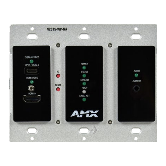
FIG. 1
N2615-WP WALLPLATE ENCODER
Installing the N2615-WP Wallplate Insert:
Follow the steps below to mount your new N2615-WP Encoder faceplate inserts.
1.
Select either the White or Black set of faceplates insert for the wallplate.
2.
Locate the faceplate insert alignment tool.
3.
Place the alignment tool around the faceplate where the insert will be applied. (Fig.
2)
4.
Remove the adhesive from faceplate insert and place the insert within the
alignment tool. (Fig. 2)
•
Ensure the LED and IO are aligned with the face insert correctly.
5.
Press inserts firmly into place for several seconds before removing alignment tool.
6.
Repeat the above process for the remaining faceplate inserts.
FIG. 2
N2615-WP WALLPLATE ENCODER
Installing the N2615-WP Wallplate Encoder:
Follow the steps below to mount your new N2615-WP Encoder into an existing three
gang electrical box. The instructions given assume the box is already installed with
Ethernet access running to it.
1.
Connect the PoE-enabled Ethernet cable to the rear connector of the N2615-WP
Encoder. This provides both network and power connection to the Encoder.
2.
Place the N2615-WP Encoder into the box and secure it with six screws (included
in shipment).
3.
Check LEDs for normal display (see the LED table at right).
4.
Attach the (customer-provided US model only) front cover plate to the unit to
complete installation.
Attaching Signal and Control Cables
The following table explains how to attach cables to the front of the Encoder.
I M PORTAN T: Encoders must be securely mounted and connected to the switch before
attaching the remaining cables.
NOTE: Any switch handling the N2615-WP Encoder video stream must be configured to
support jumbo frames. Disable the wireless adapter on your computer (it must be hard-
wired to the switch).
NMX-ENC-N2615-WP
Basic Cabling Guidelines
Connector Description
HDMI IN
Digital Video Connection
For video encoding of a digital source, connect from the source to
the Encoder port labeled HDMI IN using a video cable with an HDMI
connector (or adapter).
DP IN /
Digital Video & USB Data Connection
USB2.0
Attach a USB cable from the PC to the Encoder USB-C port labeled DP IN
/ USB2.0.
AUDIO IN -
Audio Encoding
STEREO
Insert an analog audio cable from the source into the AUDIO IN jack
(optional) or use the embedded audio from the video source.
This table shows LED states on initial power up. If not normal, check connections.
Normal
Indicator LEDs
power up
Front-Right LEDs
AUDIO*
Green
Front-Center LEDs
POWER
Green
STATUS
Green
STREAM
Green
HDCP
Yellow
LINK/ACT
Green
Front-Left LEDs
DISPLAY VIDEO*
Green
HDMI VIDEO
Green
* The LEDs for DISPLAY VIDEO and AUDIO each indicate the configured state of the
connectors (not necessarily the presence of signals through the Encoder).
Additional Buttons
The front-center section of the unit is shown in FIG. 3. This section is covered by the
cover plate once it has been installed.
ID button - Identifies the unit in N-Able.
(press and release) Can also set Encoder
back to factory defaults (press and hold 30
seconds).
RESET button - Resets Decoder's CPU.
FIG. 3
BUTTONS LOCATED ON FRONT OF UNIT BEHIND PLATE COVER
Establishing Connection
N2615-WP Encoders are shipped with DHCP as their default IP mode. The IP address is
assigned automatically based on the network DHCP server. If no DHCP server is found,
the unit will use Auto IP mode instead (with a default IP address of 169.254.xxx.xxx).
Before using your N2615-WP Encoder unit, it must be configured using the free N-Able
device management software. However, you will not be able to configure units until
they are in the same subnet as the host computer. The sample steps below show how
the required changes (to the host computer's IP settings) are made in a Windows
environment.
QUICK START GUIDE
Indicates
Configured to pass analog audio
(coupled with digital or analog video path).
PoE power is applied.
Flashing (green) when there is software activity.
On when the unit is streaming video to the network.
On when HDCP is active.
Flashing when there is Ethernet activity.
Configured to pass HDMI with embedded audio.
On when HDMI sync is detected
30
AV FOR AN IT WORLD
®
Advertisement

Subscribe to Our Youtube Channel
Related Manuals for Harman AMX NMX-ENC-N2615-WP


Summary of Contents for Harman AMX NMX-ENC-N2615-WP
- Page 1 QUICK START GUIDE NMX-ENC-N2615-WP Basic Cabling Guidelines Overview The SVSI NMX-ENC-N2615-WP Encoder Wallplate is part of the N2600 Series and used Connector Description in conjunction with N2600 Series Decoders for transmission of video, audio, control, and HDMI IN Digital Video Connection USB 2.0 over Ethernet.
- Page 2 REV: A © 2022 Harman. All rights reserved. SmartScale, NetLinx, Enova, AMX, AV FOR AN IT WORLD, and HARMAN, and their respective logos are registered trademarks of HARMAN. Oracle, Java and any other company or brand name referenced may be trademarks/registered trademarks of their respective companies.
Need help?
Do you have a question about the AMX NMX-ENC-N2615-WP and is the answer not in the manual?
Questions and answers