
Subscribe to Our Youtube Channel
Related Manuals for Harman AMX NMX-ENC-N2151


Summary of Contents for Harman AMX NMX-ENC-N2151
- Page 1 IN STR U CT IO N MAN U AL N 2 1 5 1 / N 2 2 5 1 E N C O DE RS / D E C O DE RS 4 K D I G I T A L M EDI A D I ST R I B U T I O N & S W I TC H I N G S O LU T I O N NMX- ENC- N2151 , NMX-DEC-N 2251...
- Page 2 IMPORTANT SAFETY INSTRUCTIONS READ these instructions. KEEP these instructions. HEED all warnings. FOLLOW all instructions. DO NOT use this apparatus near water. CLEAN ONLY with dry cloth. DO NOT block any ventilation openings. Install in accordance with the manufacturer's instructions. DO NOT install near any heat sources such as radiators, heat registers, stoves, or other apparatus (including amplifiers) that produce heat.
- Page 3 ESD WARNING To avoid ESD (Electrostatic Discharge) damage to sensitive components, make sure you are properly grounded before touching any internal materials. When working with any equipment manufactured with electronic devices, proper ESD grounding procedures must be followed to make sure people, products, and tools are as free of static charges as possible. Grounding straps, conductive smocks, and conductive work mats are specifically designed for this purpose.
-
Page 4: Table Of Contents
Table of Contents Table of Contents Introducing Your New N2151/N2251 4K Devices ..........6 Product Overview ......................6 Hardware Overview ......................6 Installing and Configuring Your AV Equipment ..........9 Installation Overview ......................9 Mounting Options ......................10 Surface and Wall Mounting........................10 Rack Mounting ............................ - Page 5 Table of Contents IR Page ..........................35 N-Act Page........................36 Serial Page........................37 Security Page ........................38 KVM Page......................... 39 EDID Page ........................40 Logs Page ........................41 LLDP Page ........................41 Decoder Configuration Options ...............42 Settings Page ......................... 43 Decoder Setup Section ....................
-
Page 6: Introducing Your New N2151/N2251 4K Devices
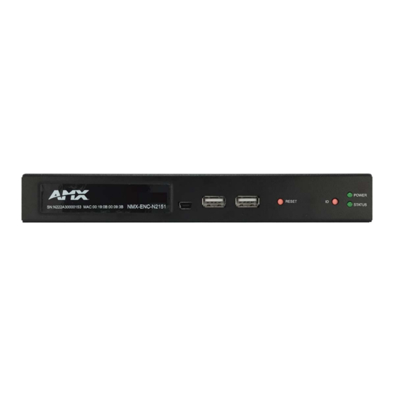
Introducing Your New N2151/N2251 4K Devices Chapter 1: Introducing Your New N2151/N2251 4K Devices Product Overview The NMX-ENC-N2151 4K Encoder and NMX-DEC-N2251 4K Decoder provide users with the industry's most versatile solution for distributing AV over a converged network at resolutions up to 4096×2160. JPEG2000 compression allows Ultra HD media to be switched and distributed over standard Gigabit Ethernet networks. - Page 7 Introducing Your New N2151/N2251 4K Devices 1) USB Mini-B Port (inactive on Decoders) 4) Device ID Discovery Button 2) USB Standard-A Ports 5) Power/Status Indicators 3) Device Reset Button Decoder Front Panel FIG. 3 1) 12VDC Input 5) IR Emitter Connection 2) Status Indicators 6) RS232 Connection 3) RJ45 Auto-Sensing Gigabit Ethernet Switch Port...
- Page 8 Introducing Your New N2151/N2251 4K Devices Front and Rear Panel Descriptions (Cont.) AUDIO 5-pin terminal Phoenix connector which provides user-selectable balanced/unbalanced, dedicated audio input (for Encoders) and output (for Decoders). HDMI IN HDMI video input (Encoders). HDMI OUT HDMI video output (Decoders). Pass thru HDMI video (Encoders). VGA IN DB-15 analog input.
-
Page 9: Installing And Configuring Your Av Equipment
Installing and Configuring Your AV Equipment Chapter 2: Installing and Conf iguring Your AV Equipment This chapter provides an installation overview as well as a detailed step-by-step process for installation. If you encounter any problems, refer to the Troubleshooting section on page 61 for help. Installation Overview The N2X51 Encoders and Decoders have multiple configuration and installation options. -
Page 10: Mounting Options
Installing and Configuring Your AV Equipment Mounting Options The N2X51 units are available in stand-alone and card versions. The stand-alone version can be free standing, surface mounted, wall mounted, or rack mounted. All cards must be rack mounted using the NMX-ACC-N9206 Card Cage (sold separately). Surface and Wall Mounting To mount your N2X51 stand-alone unit to a flat surface or wall, follow these steps: Remove the four screws from the bottom of the unit and use them to attach the mounting wings (sold separately - part... - Page 11 Installing and Configuring Your AV Equipment To install N2X51 Series cards into the N9206 Card Cage, follow these steps: Gently slide the card into cage slot. Make sure the card is properly aligned with guides. The card’s front LED indicators should align with holes in the cage’s faceplate.
-
Page 12: Step-By-Step Installation Instructions
Installing and Configuring Your AV Equipment Step-by-Step Installation Instructions This section provides step-by-step guidance for installing and configuring equipment from the N-Series product family on your network. The steps provided here assume the following to be true: There are switches operational on the network. N-Series equipment can operate on many different brands of networking equipment. - Page 13 Installing and Configuring Your AV Equipment Double-click the wired interface to your AV network, and then click the Properties button. Scroll down in the list to the Internet Protocol Version 4 (TCP/IPv4) option. Highlight it and click the Properties button. N2151/N2251 User Manual...
- Page 14 Installing and Configuring Your AV Equipment Enable the Use the following IP address option, and enter the static IP address provided to you by your network administrator. NOTE: If the computer does not need Internet access, you can simply enter a unique 169.254.xxx.xxx IP address with a 255.255.0.0 subnet mask.
- Page 15 Installing and Configuring Your AV Equipment Once the Decoders and displays are connected and powered up, the LocalPlay screen appears on the displays. NOTE: If the LocalPlay screen does not appear, refer to Chapter 5, Troubleshooting for more guidance. Step 3: Connecting Encoders to the Network and Conf iguring Stream Settings Using a Cat-5e or higher cable, connect your N2151 Encoder’s P0 port to a switch (or connect SFP+ to the P1 port).
- Page 16 Installing and Configuring Your AV Equipment Encoders are listed across the top of the page. Decoders are listed down the left side of the page. Red Text - No video source (Encoder) or no display (Decoder). Black Text - Unit is in live play mode. Red Exclamation Point (!) - N-Able cannot communicate with device.
-
Page 17: How Ip Address Changes Affect Unit Control
Installing and Configuring Your AV Equipment Changing Stream Setting FIG. 13 Repeat these steps until all Encoders are connected to the network and configured with an appropriate Stream number. NOTE: Each Encoder’s Stream number must be unique to all other Encoders on the network. NOTE: Screen-by-screen descriptions of the web interface options are provided for your reference in the Encoder Conf iguration Options section on page 24... -
Page 18: Changing Ip Addresses
Installing and Configuring Your AV Equipment Changing IP Addresses There are two ways to assign new IP addresses to your N2X51 units using N-Able: Option 1: Log in to each unit individually and make the changes on the Settings page. ... - Page 19 Installing and Configuring Your AV Equipment HDMI Cable N2151 Encoder Cat-5 Cable Network Switch Encoder Connection to Source FIG. 15 N2151/N2251 User Manual...
-
Page 20: Switching And Scaling Options
Installing and Configuring Your AV Equipment Switching and Scaling Options N-Series Encoders and Decoders make up a true AV matrix solution. In other words, one input can go to any or all outputs. Both Encoders and Decoders have internal scaling capabilities. Keep the following in mind: The input of an Encoder is the video and/or audio signal going into the Encoder. -
Page 21: Control Options
Installing and Configuring Your AV Equipment Control Options For the most part, once the initial setup is complete, you will be primarily managing/configuring the Decoders. To better understand, think of Encoders as radio stations and Decoders as car radios. The Encoders are supplying the streams and, using the Decoders, you can “tune in”... -
Page 22: Kvm Configuration
Installing and Configuring Your AV Equipment KVM Conf iguration The N2151 Encoders and N2251 Decoders are KVM-capable. By default, USB connections are enabled and configured to follow video switching. Basic Setup Follow these steps for basic KVM configuration: On the N2151 Encoder, connect the USB Mini-B port to the computer to be controlled. Connect the computer’s video output to the Encoder’s HDMI IN port. - Page 23 Installing and Configuring Your AV Equipment NOTE: These options can also be managed in the unit’s GUI (by clicking KVM from the main menu as shown in Figure 18). It is important to note that many of these options only appear on the KVM page when USB is enabled as well as KVM Advanced Settings. KVM Page on page 58 for more details.
-
Page 24: Encoder Configuration Options
Encoder Configuration Options Chapter 3: Encoder Conf iguration Options This chapter defines N2151 Encoder configuration options. For ease of navigation, it is organized to reflect the graphical user interface (GUI). From any main page in the GUI, you can access all other main pages by clicking the links in the top navigation bar. Figure 19 shows the navigation bar and provides hot links to the sections of this chapter which describe each main page. -
Page 25: Settings Page
Encoder Configuration Options Settings Page Click the Settings link at the top of any of the main web pages to access the page shown in Figure 20. This page is divided into several sections and also has links to other dialog boxes for additional configuration options. Refer to the following sections for detailed descriptions: Encoder Setup Section on page 26 ... -
Page 26: Encoder Setup Section
Encoder Configuration Options Encoder Setup Section The Encoder Setup section of the Settings page is shown in Figure 21. Options are described in Table Encoder Setup Section FIG. 21 Settings Page: Encoder Setup Section TABLE 1 Option Description Notes Device Name Enter a user-friendly name for the unit. - Page 27 Encoder Configuration Options Settings Page: Encoder Setup Section (Cont.) TABLE 1 Option Description Notes Video Source Select which input port is encoding video. Selecting HDMI/VGA declares HDMI as the primary port and VGA as the secondary port (when there is no HDMI input).
-
Page 28: Advanced Settings
Encoder Configuration Options Advanced Settings The section of the Settings page shown in Figure 22 is displayed when you click the Advanced Settings link. Options are described Table Advanced Settings FIG. 22 Settings Page: Advanced Settings TABLE 2 Option Description Notes Settings Lock Enable to lock the Encoder IP settings and stream... - Page 29 Encoder Configuration Options Settings Page: Advanced Settings (Cont.) TABLE 2 Option Description Notes Audio Encrypt Enable to encrypt the audio stream. Encryption is on by default. Turn off encryption to allow for compatibility with other devices that require a decrypted stream. Brightness Use sliders to raise or lower RGB values of the Encoder Only affects analog video.
-
Page 30: Rs232 Settings
Encoder Configuration Options RS232 Settings The section of the Settings page shown in Figure 23 is displayed when you click the RS232 Settings link. Options are described in Table RS232 Settings FIG. 23 Settings Page: RS232 Settings TABLE 3 Option Description RS232 Baud Rate Select the appropriate baud rate for the RS232 serial interface. -
Page 31: Status Section
Encoder Configuration Options Settings Page: Network Setup Settings (Cont.) TABLE 4 Option Description Notes Ping Test Test connection by specifying an IP address or URL to ping. Click the Ping link to initiate the test. Trial Save Click to initially save IP address changes. Once you log in to the unit using the new address, you will be able to confirm and accept the changes permanently. -
Page 32: Change Password Section
Encoder Configuration Options Change Password Section To change the N2151 Encoder interface password (for admin-level access) enter the current password in the field labeled Old Password, and enter a new password in the New Password and Conf irm Password fields. Click Change PW to accept the new password. -
Page 33: Hdmi Pass Thru Settings Section
Encoder Configuration Options HDMI Pass Thru Settings Section The section of the Settings page show in Figure 28 is displayed when you click the HDMI Pass Thru Settings link. Options are described in Table HDMI Pass Thru Settings FIG. 28 Settings Page: HDMI Pass Thru Settings TABLE 7 Option... -
Page 34: Hostplay Page
Encoder Configuration Options HostPlay Page Click the HostPlay link at the top of any of the main web pages to access the page shown in Figure 29. This page allows you to upload new images to the Encoders and configure the image playlists. The playlist will be shown on the display when no video is being transmitted or received. -
Page 35: Ir Page
Encoder Configuration Options IR Page Click the IR link at the top of any of the main web pages to access the page shown in Figure 30. This page allows you to upload and execute IR Pronto codes so that other vendor’s devices can be controlled through the Encoder’s IR connector. Commands can be saved for future use and executed later. -
Page 36: N-Act Page
Encoder Configuration Options N-Act Page Click the N-Act link at the top of any of the main web pages to access the page shown in Figure 31. This page allows you to create command lists which are performed automatically by the unit based on power or video connection (without the use of an outside controller). -
Page 37: Serial Page
Encoder Configuration Options Serial Page Click the Serial link at the top of any of the main web pages to access the page shown in Figure 32. This page allows you to upload and execute commands used for direct control of serial devices. Commands may be saved for future use and executed later. The Serial Code menu lists all saved commands. -
Page 38: Security Page
Encoder Configuration Options Security Page Click the Security link at the top of any of the main web pages to access the page shown in Figure 33. This page allows you to force HTTPS connections and set up a password for stream encryption. To successfully display an encrypted Encoder stream on a Decoder, the Decoder must match the Encoder password. -
Page 39: Kvm Page
Encoder Configuration Options KVM Page Click the KVM link at the top of any of the main web pages to access the N-Series KVM page. You must check the USB Enable box at the top to see the page shown in Figure 34. -
Page 40: Edid Page
Encoder Configuration Options EDID Page Click the EDID link at the top of any of the main web pages to access the page shown in Figure 35. Every display has stored information that it communicates to the output device. This page allows you to view that information.Options are described in Table 14. -
Page 41: Logs Page
Encoder Configuration Options EDID Page Options (Cont.) TABLE 14 Option Description Set EDID to Pass-thru Set the EDID to the pass-thru EDID of the connected display to HDMI OUT. Reset EDID For Digital, choose a standard EDID from the drop-down menu and click Reset EDID to apply. For Analog, no selection is necessary. -
Page 42: Decoder Configuration Options
Decoder Configuration Options Chapter 4: Decoder Conf iguration Options This chapter defines N2251 Decoder configuration options. For ease of navigation, it is organized to reflect the graphical user interface (GUI). As explained previously in the Encoder Conf iguration Options section on page 24, you can access the GUI main pages by clicking the links in the top navigation bar. -
Page 43: Settings Page
Decoder Configuration Options Settings Page Click the Settings link at the top of any of the main web pages to access the page shown in Figure 39. This page is divided into several sections and also has links to other dialog boxes for additional configuration options. Refer to the following sections for detailed descriptions: Decoder Setup Section on page 44 ... -
Page 44: Decoder Setup Section
Decoder Configuration Options Decoder Setup Section The Decoder Setup section of the Settings page is shown in Figure 40. Options are described in Table Decoder Setup Section FIG. 40 Settings Page: Decoder Setup Section TABLE 15 Option Description Notes Device Name Enter a user-friendly name for the unit. - Page 45 Decoder Configuration Options Settings Page: Decoder Setup Section (Cont.) TABLE 15 Option Description Notes Mute Enable to mute output audio. Lineout Volume This slider controls the output gain on the analog audio By default, this setting controls both the left and right output.
-
Page 46: Advanced Settings
Decoder Configuration Options Advanced Settings The section of the Settings page shown in Figure 41 is displayed when you click the Advanced Settings link. Options are described Table Advanced Settings FIG. 41 Settings Page: Advanced Settings TABLE 16 Option Description Notes Settings Lock Enable to lock the Decoder IP settings and stream... - Page 47 Decoder Configuration Options Settings Page: Advanced Settings (Cont.) TABLE 16 Option Description Notes HDMI off on stream loss Select to disable the video output drive when the video stream is not available. HDMI Enable Select to enable output video. Invert HDMI Horizontal Select to invert the polarity of the horizontal sync Sync signal driven to the display device.
-
Page 48: Rs232 Settings
Decoder Configuration Options RS232 Settings The section of the Settings page shown in Figure 42 is displayed when you click the RS232 Settings link. Options are described in Table RS232 Settings FIG. 42 Settings Page: RS232 Settings TABLE 17 Option Description RS232 Baud Rate Select the appropriate baud rate for the RS232 serial interface. -
Page 49: Status Section
Decoder Configuration Options Settings Page: Network Setup Settings (Cont.) TABLE 18 Option Description Notes Ping Test Test connection by specifying an IP address or URL to ping. Click the Ping link to initiate the test. Trial Save Click to initially save IP address changes. Once you log in to the unit using the new address, you will be able to confirm and accept the changes permanently. -
Page 50: Change Password Section
Decoder Configuration Options Change Password Section To change the N2251 Decoder interface password (for admin-level access) enter the current password in the field labeled Old Password, and enter a new password in the New Password and Conf irm Password fields. Click Change PW to accept the new password. -
Page 51: Audio Downmixer Settings
Decoder Configuration Options Audio Downmixer Settings The section of the Settings page shown in Figure 47 is displayed when you click the Audio Downmixer Settings link. Options are described in Table Audio Downmixer Settings FIG. 47 Settings Page: Audio Downmixer Settings TABLE 22 Option Description... - Page 52 Decoder Configuration Options Crop/Pan/Zoom Page Click the Crop/Pan/Zoom link at the top of any of the main web pages to access the page shown in Figure 48. This page allows you to customize the viewable portion of the input. See Table 23 for option descriptions.
-
Page 53: Localplay Page
Decoder Configuration Options LocalPlay Page Click the LocalPlay link at the top of any of the main web pages to access the screen shown in Figure 49. This page allows you to upload new images to the Decoders and configure the image playlists. The playlist will be shown on the display when no video is being transmitted or received. -
Page 54: Ir Page
Decoder Configuration Options LocalPlay Page Options (Cont.) TABLE 24 Option Description Delete Image(s) Delete the selected image file from the playlist. Delete Audio Delete the selected audio file from the playlist. IR Page Click the IR link at the top of any of the main web pages to access the page shown in Figure 50. -
Page 55: N-Act Page
Decoder Configuration Options N-Act Page Click the N-Act link at the top of any of the main web pages to access the page shown in Figure 51. This page allows you to create command lists which are performed automatically by the unit based on power or video connection (without the use of an outside controller). -
Page 56: Serial Page
Decoder Configuration Options Serial Page Click the Serial link at the top of any of the main web pages to access the page shown in Figure 52. This page allows you to upload and execute commands used for direct control of serial devices. Commands may be saved for future use and executed later. The Serial Code menu lists all saved commands. -
Page 57: Security Page
Decoder Configuration Options Security Page Click the Security link at the top of any of the main web pages to access the page shown in Figure 53. This page allows you to force HTTPS connections and set up a password for stream encryption. To successfully display an encrypted Encoder stream on a Decoder, the Decoder must match the Encoder password. -
Page 58: Kvm Page
Decoder Configuration Options KVM Page Click the KVM link at the top of any of the main web pages to access the N-Series KVM page. You must check the USB Enable box at the top to see the page shown in Figure 54. -
Page 59: Edid Page
Decoder Configuration Options KVM Page Options (Cont.) TABLE 29 Option Description Export KVM CSV Click the Download KVM CSV Export link to retrieve the current KVM CSV configuration file. Reset USB and KVM Resets all USB and KVM settings. Settings EDID Page Click the EDID link at the top of any of the main web pages to access the page shown in Figure... -
Page 60: Logs Page
Decoder Configuration Options Logs Page Click the Logs link at the top of any of the main web pages to access the page shown in Figure 56. The Logs page displays a command log that lists all TCP and UDP messages the unit receives. It also displays the web browser’s IP address and gives you options to Refresh and Reset Logs. -
Page 61: Troubleshooting
Chapter 5: Troubleshooting This chapter contains possible solutions to some common issues. Should you encounter any problems not covered by these guidelines, please contact technical support via email (svsisupport@harman.com) or call 256.461.7143 x9900. You can also visit our support webpage at support.svsiav.com. -
Page 62: Series Default Local/Host Play Troubleshooting Screens
Troubleshooting Series Default Local/Host Play Troubleshooting Screens This section shows and defines the status screens displayed by N2x51 Series devices. FIG. 58 Host Play Screen Displayed when Decoder..and Encoder..Notes • is set to view an Encoder stream on •... - Page 63 Troubleshooting FIG. 60 Unsupported Input Resolution Screen Displayed when Decoder..and Encoder..Notes • is set to view an Encoder stream on • is being fed a video resolution that This screen can be useful to show you that the the network it does not support Decoder is receiving the stream from the...
- Page 64 Troubleshooting FIG. 62 Video Source Outputting Restricted Content Screen Displayed when Decoder..and Encoder..Notes • is receiving a stream from an • is receiving HDCP-protected Please call Technical Support to enable this feature. Encoder content from the video source, but is not set up to pass it.
-
Page 65: Appendix A: Minimum Network Requirements
TCN flood protocol will cause unnecessary backplane and bandwidth usage when adding or removing a device on the network. This can cause stream interruptions as the flooding sweeps through the network. Should you encounter any problems not covered by these guidelines, please contact technical support via email (svsisupport@harman.com) or call 256.461.7143 x9900. N2151/N2251 User Manual... - Page 66 © 2016 Harman. All rights reserved. AMX, AV FOR AN IT WORLD, and HARMAN, and their respective logos are registered trademarks of HARMAN. Last Revised: Oracle, Java and any other company or brand name referenced may be trademarks/registered trademarks of their respective companies.
Need help?
Do you have a question about the AMX NMX-ENC-N2151 and is the answer not in the manual?
Questions and answers