
Subscribe to Our Youtube Channel
Related Manuals for Harman AMX N2600 Series


Summary of Contents for Harman AMX N2600 Series
- Page 1 INSTRUCTION MANUAL N2600 SERIES NMX-ENC-N2615D-WP WALLPLATE ENCODERS/NMX-DEC-N2625D-WP WALLPLATE DECODERS NMX-ENC-N2615D-WP-NA, NMX-DEC-N2625D-WP-NA NMX-ENC-N2615D-WP-EK, NMX-DEC-N2625D-WP-EK...
- Page 2 IMPORTANT SAFETY INSTRUCTIONS READ these instructions. KEEP these instructions. HEED all warnings. FOLLOW all instructions. DO NOT use this apparatus near water. CLEAN ONLY with dry cloth. DO NOT block any ventilation openings. Install in accordance with the manufacturer's instructions. DO NOT install near any heat sources such as radiators, heat registers, stoves, or other apparatus (including amplifiers) that produce heat.
- Page 3 EU COMPLIANCE INFORMATION: Hereby, Harman Professional, Inc. declares that the equipment is in compliance with the following: European Union Low Voltage Directive 2014/35/EU; European Union EMC Directive 2014/30/EU; European Union Restriction of Hazardous Substances Recast (RoHS2) Directive 2011/65/EU and as amended by 2015/863.
- Page 4 Manufacturer Information: HARMAN Professional, Inc. Address: 8500 Balboa Blvd. Northridge, CA 91329 USA EU Regulatory Contact: Harman Professional Denmark ApS Olof Palmes Allé 44, 8200 Aarhus N, Denmark UK Regulatory Contact: Harman Professional Solutions 2 Westside, London Road, Apsley, Hemel Hempstead, HP3 9TD, UK...
-
Page 5: Table Of Contents
Table of Contents Introducing Your New N2600 Series Devices ................8 Product Overview............................... 8 Hardware Overview ..............................8 Installing and Configuring Your AV Equipment ................ 11 Installation Overview ..............................11 Step-by-Step Installation Instructions ..........................12 Step 1: Setting Up Your Host Computer ..........................12 Step 2: Connecting Decoders to the Network ........................14 Step 3: Connecting Encoders to the Network and Configuring Stream Settings.................15 Step 4: Configuring Decoder and Encoder IP addresses (if needed) .....................17... - Page 6 Playlist Section – Playlist Setup ............................40 Security Page ................................41 Web Page Section – General Setup .............................42 Security Certificates Section – General Setup ..........................43 User Security Details Section – Users Setup ...........................44 LDAP Section – LDAP Setup .............................45 Control Page ................................46 N-Act Events –...
- Page 7 RS232 Settings – Serial Setup ............................86 Serial Settings – Serial Setup ............................87 IR Command – IR Setup ..............................88 IR Passthrough Settings – IR Setup ............................89 N-Act Events – N-Act ..............................90 USB Setting – KVM/USB ..............................91 System Page ................................92 Command Log – Log ..............................93 Debug Log –...
-
Page 8: Introducing Your New N2600 Series Devices
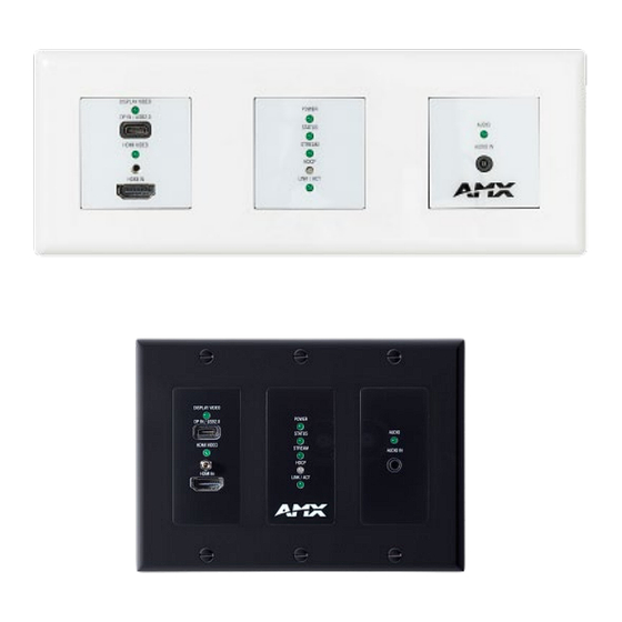
Introducing Your New N2600 Series Devices Introducing Your New N2600 Series Devices Product Overview The N2600 AV over IP Series belongs to the N-Series product family from AMX and consists of N2612 Encoders, N2622 Decoders, N2615D Wallplate Encoders and N2625D Wallplate Decoders. This series provides a flexible, feature-rich, simple-to- deploy digital media distribution and switching solution that can be used in 4K applications with resolutions up to 4096x2160, with support for HDCP 2.2. - Page 9 Introducing Your New N2600 Series Devices 1) Analog Audio Out 6) USB-A HID Connector 2) HDMI Out 7) USB-A, USB 2.0 or HID 3) Device ID Discovery Button 8) IR Output 4) Device Reset Button 9) RS232 Connector 5) LED Status Indicators FIG.
- Page 10 Introducing Your New N2600 Series Devices Wallplate Encoder and Decoder Panel Descriptions Encoder Panel DISPLAY VIDEO LED On (green) when USB-C is detected USB-C port For Video/KVM/USB 2.0 support. HDMI VIDEO LED On (green) when HDMI is detected HDMI IN HDMI video input.
-
Page 11: Installing And Configuring Your Av Equipment
Installing and Configuring Your AV Equipment Installing and Configuring Your AV Equipment This chapter provides an installation overview as well as a detailed step-by-step process for installation. If you encounter any problems, refer to the Troubleshooting section on page 100 for help. Installation Overview The N2600 Encoders and Decoders have multiple configuration and installation options. -
Page 12: Step-By-Step Installation Instructions
Installing and Configuring Your AV Equipment Step-by-Step Installation Instructions This section provides step-by-step guidance for installing and configuring equipment from the N-Series product family on your network. The steps provided here assume the following to be true: NOTE: For a more detailed requirements list, refer to on page 105. - Page 13 Installing and Configuring Your AV Equipment Scroll down in the list to the Internet Protocol Version 4 option. Highlight it and click the Properties button. N2615-WP/N2625-WP Manual...
-
Page 14: Step 2: Connecting Decoders To The Network
Installing and Configuring Your AV Equipment address option and enter the static IP address provided to you by your network administrator. NOTE: If the computer does not need Internet access, you can simply enter a unique 169.254.xxx.xxx IP address with a 255.255.0.0 subnet mask. -
Page 15: Step 3: Connecting Encoders To The Network And Configuring Stream Settings
Installing and Configuring Your AV Equipment Once the Decoders and displays are connected and powered up, the LocalPlay screen appears on the displays. NOTE: If the LocalPlay screen does not appear, refer to the chapter Troubleshooting on page 100 for more guidance. NOTE: In order for the unit to receive PoE+, it must be connected to a switch or other equipment that has a PoE+ PSE (Power Sourcing Equipment) port. - Page 16 Installing and Configuring Your AV Equipment Encoders listed along the top Decoders listed along the bottom Red Text – Black Text – No Video source (Encoder) or no display (Decoder) Unit is in live play mode. Red Explanation Point (!) – –...
-
Page 17: Step 4: Configuring Decoder And Encoder Ip Addresses (If Needed)
Installing and Configuring Your AV Equipment FIG. 7 Changing Stream Setting Repeat these steps until all Encoders are connected to the network and configured with an appropriate Stream number. NOTE: Each Encoder’s Stream number must be unique to all other Encoders on the network. NOTE: Screen-by-screen descriptions of the web interface options are provided for your reference in the Encoder Configuration Options section... -
Page 18: Option 2: Assigning Ip Addresses To Multiple Units (Using Csv Files)
Installing and Configuring Your AV Equipment FIG. 8 IP Setup of the Network settings Click the Save button. Return to the Settings page through the newly configured IP address. Option 2: Assigning IP Addresses to Multiple Units (using CSV files) N-Able has the ability to export and import CSV files. -
Page 19: Step 5: Connecting Encoders To An Input Source
Installing and Configuring Your AV Equipment Step 5: Connecting Encoders to an Input Source Having already connected the Encoder(s) to the network and made the appropriate settings changes (as described in Step 3 Step 4), you can now connect to the appropriate AV source(s). This connection from an Encoder HDMI IN port to an input source is accomplished using either an HDMI cable, USB-C cable or DVI-I (through adapter). -
Page 20: Switching And Scaling Options
Installing and Configuring Your AV Equipment Switching and Scaling Options N-Series Encoders and Decoders make up a true AV matrix solution. In other words, one input can go to any or all outputs. Decoders have internal scaling capabilities. Keep the following in mind: The input of an Encoder is the video and/or audio signal going into the Encoder. -
Page 21: Control Options
Installing and Configuring Your AV Equipment Control Options For the most part, once the initial setup is complete, you will be primarily managing/configuring the Decoders. To better understand, think of Encoders as radio stations and Decoders as car radios. The Encoders are supplying the streams and, using the Decoders, you can “tune in”... -
Page 22: Encoder Configuration Options
Encoder Configuration Options Encoder Configuration Options This chapter defines N2615D Encoder configuration options. For ease of navigation, it is organized to reflect the graphical user interface (GUI). From any main page in the GUI, you can access all other main pages by clicking the links in the top navigation bar. Below shows the navigation bar and provides hot links to the sections of this chapter which describe each main page. -
Page 23: Home Page
Encoder Configuration Options Home Page Click the Home link at the top of any of the main web pages to access the page shown. This page is divided into several sections and has links to other dialog boxes for additional configuration options. Refer to the following sections for detailed descriptions: Stream Setup Settings Section on page 24 ... -
Page 24: Stream Setup Section
Encoder Configuration Options Stream Setup Section The Stream Setup section of the Home page is shown. FIG. 13 Device Settings Section TABLE 1 Home Page: Stream Settings Section Option Description Notes When Enabled/Disabled and after pressing save will Dante AV Mode When enabled, it will allow the Dante Video and Audio channels to be discover able in the Dante Controller reboot the unit for the settings to take effect. -
Page 25: Management Setup Settings
Encoder Configuration Options Management Setup Settings The Management Setup section of the Home page is shown. FIG. 14 Management Setup Settings TABLE 2 Home Page: Management Setup Settings Option Description Notes Settings Lock Enable to lock the Encoder IP settings and stream number, preventing automated processes (from N-Able or N-Command) from occurring. -
Page 26: Current Source Section
Encoder Configuration Options Current Source Section The Current Source section of the Home page is shown. FIG. 15 Current Source Section TABLE 3 Home Page: Current Source Section Option Description Notes When enabled the current source will be shown in the below Preview Image The preview image is updated approximately image preview area. -
Page 27: General Setup Section
Encoder Configuration Options General Setup Section The General Setup section of the Home page is shown. FIG. 16 General Setup Section TABLE 4 Home Page: General Setup Section Option Description Notes Enable Send Status Enables the encoder to send a periodic status packet to the Send Status Address listed. -
Page 28: Network Page
Encoder Configuration Options Network Page Click the Network link at the top of any of the main web pages to access the page shown. This page is divided into several sections and has links to other dialog boxes for additional configuration options. Refer to the following sections for detailed descriptions: IP Setup Settings Section on page 29 ... -
Page 29: General Section -Ip Setup
Encoder Configuration Options General Section –IP Setup The General Section of the IP Setup on the Network page is shown. FIG. 18 General Section TABLE 5 Network Page: General Section of IP Setup Option Description Notes Type in the domain name of the network if needed Domain DNS IP 1 IP address of a DNS server. -
Page 30: Ipv4 Section -Ip Setup
Encoder Configuration Options IPv4 Section –IP Setup The IPv4 section of the IP Setup on the Network page is shown. FIG. 19 IPv4 Section TABLE 6 Network Page: IPv4 Section of IP Setup Option Description Notes Used to select either DHCP or Static IP Address mode. DHCP / Static IP Address IP Address... -
Page 31: Ipv6 Section -Ip Setup
Encoder Configuration Options IPv6 Section –IP Setup The IPv6 section of the IP Setup on the Network page is shown. FIG. 20 IPv6 Section TABLE 7 Network Page: IPv6 Section of IP Setup Option Description Notes When enabled the unit will attempt to obtain a DHCP IPv6 Enable / Disable Disabled by default, Requires an IPv6 DHCP address. -
Page 32: Date/Time
Encoder Configuration Options Date/Time The Date/Time section of the Network page is shown. FIG. 21 Date/Time Section TABLE 8 Network Page: Date/Time Option Description Notes Displays the current date and time of the unit. Current Date and Time Used to select the offset for the NTPP time. Time Zone Used to select the NTP server connection One NTP must be selected for NTP to be... - Page 33 Encoder Configuration Options 802.1x The 802.1x section of the Network page is shown. FIG. 22 802.1x Section TABLE 9 Network Page: 802.1x Option Description Notes When enabled will allow the device to be used with 802.1x IEEE 802.1x network configurations. Authentication Status Displays the current port connection as either Disabled,...
-
Page 34: Video/Audio Page
Encoder Configuration Options Video/Audio Page Click the Video/Audio link at the top of any of the main web pages to access the page shown. This page is divided into several sections and has links to other dialog boxes for additional configuration options. Refer to the following sections for detailed descriptions: Video Settings on page 35... -
Page 35: Hdmi Video Section -Video Section
Encoder Configuration Options HDMI Video Section –Video section The HDMI Video section of the of the Video section on the Video/Audio page is shown. FIG. 24 HDMI Video Section TABLE 10 Video/Audio: HDMI Video section of the Video tab Option Description Notes HDCP Support... -
Page 36: Current Source Section - Video Section
Encoder Configuration Options Current Source Section – Video section The Current Source section of the Video section on the Video/Audio page is shown. FIG. 25 Current Source Section TABLE 11 Video/Audio: Current Source section of the Video tab Option Description Notes Current Source Status field displaying one of three options showing the current... -
Page 37: Status - Video Section
Encoder Configuration Options Status – Video section The Status section of the Video section on the Video/Audio page is shown. FIG. 26 Status Section TABLE 12 Video/Audio: Status section of the HDMI Pass-thru section of the Video tab Option Description Notes HDMI Status Status field displaying connection status of the HDMI input port... -
Page 38: Audio Settings Section - Audio Setup
Encoder Configuration Options Audio Settings Section – Audio Setup The Audio Settings section of the Audio on the Video/Audio page is shown. FIG. 27 Audio Section TABLE 13 Network Page: Audio Section of Audio Setup Option Description Notes Drop down list containing two selections. Audio Source HDMI: Play audio coming from the HDMI input Analog: Play audio coming from the Analog audio input... -
Page 39: Edid Section - Edid Setup
Encoder Configuration Options EDID Section – EDID Setup The EDID section of the EDID on the Video/Audio page is shown. FIG. 28 EDID Section TABLE 14 Network Page: Audio Section of Audio Setup Option Description Notes EDID (drop down) Select what EDID information to display. HDMI: Displays EDID information connected to the Encoder’s HDMI input. -
Page 40: Playlist Section - Playlist Setup
Encoder Configuration Options Playlist Section – Playlist Setup The Playlist section of the Playlist on the Video/Audio page is shown. FIG. 29 Playlist Section TABLE 15 Playlist Page: Playlist Section of Playlist Setup Option Description Notes Dropdown containing Playlists 1-8 to be selected to work with. Playlist TABLE 16 Playlist Page: Playlist X Section of Playlist Setup... -
Page 41: Security Page
Encoder Configuration Options Security Page Click the Security link at the top of any of the main web pages to access the page shown. This page is divided into several sections and has links to other dialog boxes for additional configuration options. Refer to the following sections for detailed descriptions: General Settings Section on page 42 ... -
Page 42: Web Page Section - General Setup
Encoder Configuration Options Web Page Section – General Setup The Web Page section of the General on the Security page is shown. FIG. 31 Web Page Section TABLE 18 Security Page: Web Page Section of General Option Description Notes When enabled will force the web page access to always be Force HTTPS HTTPS Wen enabled will cause the web pages to fail to load... -
Page 43: Security Certificates Section - General Setup
Encoder Configuration Options Security Certificates Section – General Setup The Security Certificates section of the General on the Security page is shown. FIG. 32 Security Certificates Section TABLE 19 Security Page: Security Certificates Section of General Option Description Notes Three options exist for the drop down: Type of Certificate CA Certificate Client Certificate... -
Page 44: User Security Details Section - Users Setup
Encoder Configuration Options User Security Details Section – Users Setup The Security Certificates section of the Users on the Security page is shown. FIG. 33 User Security Details Section TABLE 20 Security Page: User Security Details Section of Users Option Description Notes Input the new password for the Administrator account... -
Page 45: Ldap Section - Ldap Setup
Encoder Configuration Options LDAP Section – LDAP Setup The LDAP section of the LDAP on the Security page is shown. FIG. 34 LDAP Section TABLE 21 Security Page: LDAP Section of LDAP Option Description Notes When enabled will allow the device to connect to an LDAP server. LDAP Enabled LDAP/LDAPS URL If using LDAP type ldap://<IP>:Port... -
Page 46: Control Page
Encoder/Decoder Configuration Options Control Page Click the Control link at the top of any of the main web pages to access the page shown. This page is divided into several sections and has links to other dialog boxes for additional configuration options. Refer to the following sections for detailed descriptions: N-Act Settings on page 47 ... -
Page 47: N-Act Events - N-Act
Encoder/Decoder Configuration Options N-Act Events – N-Act The N-Act Events Settings section of the N-Act page is shown. FIG. 36 N-Act Events Section TABLE 22 N-Act Page: N-Act Events Section Option Description Notes Enable N-Act Events Used to enable the N-Act events Power On Event Event is triggered once the device is powered on and running Video Cable... -
Page 48: Kvm/Usb 2.0 Setting - Kvm/Usb
Encoder/Decoder Configuration Options KVM/USB 2.0 Setting – KVM/USB The USB Settings section of the KVM/USB on the Control page is shown. FIG. 37 USB Settings Section TABLE 23 Control Page: USB Settings Section of USB Option Description Notes When enabled will allow a decoder USB 2.0 signal to be received. Up to 4 decoders can connect to a single USB 2.0 Enable encoder for USB 2... -
Page 49: System Page
Encoder/Decoder Configuration Options System Page Click the System link at the top of any of the main web pages to access the page shown. This page is divided into several sections and has links to other dialog boxes for additional configuration options. Refer to the following sections for detailed descriptions: Logs Section on page 50 ... -
Page 50: Command Log - Log
Encoder/Decoder Configuration Options Command Log – Log The Command Log section of the Log on the System page is shown. FIG. 39Command Log Section TABLE 24 System Page: Command Log Section of Log Option Description Notes When pressed will cleat the Command Log history table Reset Logs N2615D-WP/N2625D-WP Manual... -
Page 51: Debug Log - Log
Encoder/Decoder Configuration Options Debug Log – Log The Debug Log section of the Log on the System page is shown. FIG. 40 Debug Log Section TABLE 25 System Page: Debug Log Section of Log Option Description Notes When pressed will begin enhanced log gathering Used when troubleshooting an issue with tech Start Debug Log support... -
Page 52: Syslog Settings - Log
Encoder/Decoder Configuration Options Syslog Settings – Log The Syslog Settings section of the Log on the System page is shown. FIG. 41 Debug Log Section TABLE 26 System Page: Debug Log Section of Log Option Description Notes Syslog Server Enable When pressed will enable the Syslog server function IPv4 address of the Syslog Server to connect to Syslog Server Port used to connect to Syslog Server... -
Page 53: Link Layer Discovery Protocol (Lldp) - Status
Encoder/Decoder Configuration Options Link Layer Discovery Protocol (LLDP) – Status The LLDP section of the Status on the System page is shown. FIG. 42 LLDP Section TABLE 27 System Page: LLDP Section of Status Option Description Notes Mac address of the network switch Switch Mac Name of the network switch Switch Name... -
Page 54: Status - Status
Encoder/Decoder Configuration Options Status – Status The Status section of the Status on the System page is shown. FIG. 43 Status Section TABLE 28 System Page: Status Section of Status Option Description Notes Displays the status of the HDMI input as either Connected or HDMI Status Disconnected Displays the resolution detected on the HDMI Input... -
Page 55: Current Source - Status
Encoder/Decoder Configuration Options Current Source – Status The Current Source section of the Status on the System page is shown. FIG. 44 Current Source Section TABLE 29 System Page: Current Source of Status Option Description Notes Current Source Displays the current source selected. Auto: Last source plugged in is the active source HDMI: HDMI In is the active source USB-C: USB-C In is the active source... -
Page 56: Software - Status
Encoder/Decoder Configuration Options Software – Status The Software section of the Status on the System page is shown. FIG. 45 Current Source Section TABLE 30 System Page: Current Source of Status Option Description Notes Displays the model of the N2600 device. Model Displays the serial number of the Encoder. -
Page 57: Decoder Configuration Options
Encoder/Decoder Configuration Options Decoder Configuration Options This chapter defines N2625 Decoder configuration options. For ease of navigation, it is organized to reflect the graphical user interface (GUI). As explained previously in the Encoder Configuration Options section on page 22, you can access the GUI main pages by clicking the links in the top navigation bar. -
Page 58: Home Page
Encoder/Decoder Configuration Options Home Page Click the Home link at the top of any of the main web pages to access the page shown. This page is divided into several sections and has links to other dialog boxes for additional configuration options. Refer to the following sections for detailed descriptions: Stream Setup Settings Section on page 59 ... -
Page 59: Stream Setup Section
Encoder/Decoder Configuration Options Stream Setup Section The Stream Setup section of the Home page is shown. FIG. 48 Device Settings Section TABLE 31 Home Page: Stream Settings Section Option Description Notes More descriptive names in this field help you organize Device Name Enter a user-friendly name for the unit. -
Page 60: Management Setup Settings
Encoder/Decoder Configuration Options Management Setup Settings The Management Setup section of the Home page is shown. FIG. 49 Management Setup Settings TABLE 32 Home Page: Management Setup Settings Option Description Notes Settings Lock Enable to lock the Encoder IP settings and stream number, preventing automated processes (from N-Able or N-Command) from occurring. -
Page 61: Current Source Section
Encoder/Decoder Configuration Options Current Source Section The Current Source section of the Home page is shown. FIG. 50 Current Source Section TABLE 33 Home Page: Current Source Section Option Description Notes When enabled, the current source will be shown in the below The preview image is updated approximately Preview Image image preview area. -
Page 62: General Setup Section
Encoder/Decoder Configuration Options General Setup Section The General Setup section of the Home page is shown. FIG. 51 General Setup Section TABLE 34 Home Page: General Setup Section Option Description Notes When enabled, will send IGMP Join messages when no IGMP Join on stream incoming stream is detected. -
Page 63: Network Page
Encoder/Decoder Configuration Options Network Page Click the Network link at the top of any of the main web pages to access the page shown. This page is divided into several sections and has links to other dialog boxes for additional configuration options. Refer to the following sections for detailed descriptions: IP Setup Settings Section on page 64 ... -
Page 64: General Section -Ip Setup
Encoder/Decoder Configuration Options General Section –IP Setup The General Section of the IP Setup on the Network page is shown. FIG. 53 General Section TABLE 35 Network Page: General Section of IP Setup Option Description Notes Type in the domain name of the network if needed Domain DNS IP 1 IP address of a DNS server. -
Page 65: Ipv4 Section -Ip Setup
Encoder/Decoder Configuration Options IPv4 Section –IP Setup The IPv4 section of the IP Setup on the Network page is shown. FIG. 54 IPv4 Section TABLE 36 Network Page: IPv4 Section of IP Setup Option Description Notes Used to select either DHCP or Static IP Address mode. DHCP / Static IP Address IP Address... -
Page 66: Ipv6 Section -Ip Setup
Encoder/Decoder Configuration Options IPv6 Section –IP Setup The IPv6 section of the IP Setup on the Network page is shown. FIG. 55 IPv6 Section TABLE 37 Network Page: IPv6 Section of IP Setup Option Description Notes When enabled the unit will attempt to obtain a DHCP IPv6 Disabled by default, Requires an IPv6 DHCP Enable / Disable address. -
Page 67: Date/Time
Encoder/Decoder Configuration Options Date/Time The Date/Time section of the Network page is shown. FIG. 56 Date/Time Section TABLE 38 Network Page: Date/Time Option Description Notes Used to select the NTP server connection Select Edit When selected will allow editing of that name server information. When selected will open a pop-up allowing to input information Add Server for the NTP server... - Page 68 Encoder/Decoder Configuration Options 802.1x The 802.1x section of the Network page is shown. FIG. 57 802.1x Section TABLE 39 Network Page: 802.1x Option Description Notes When enabled will allow the device to be used with 802.1x IEEE 802.1x network configurations. Authentication Status Displays the current port connection as either Disabled,...
-
Page 69: Video/Audio Page
Encoder/Decoder Configuration Options Video/Audio Page Click the Video/Audio link at the top of any of the main web pages to access the page shown. This page is divided into several sections and has links to other dialog boxes for additional configuration options. Refer to the following sections for detailed descriptions: Video Settings on page 70... -
Page 70: Hdmi Video Section -Video Section
Encoder/Decoder Configuration Options HDMI Video Section –Video section The HDMI Video section of the Video section on the Video/Audio page is shown. FIG. 59 HDMI Video Section TABLE 40 Video/Audio: General Video section of the Video tab Option Description Notes Used to Enable or Disable the HDMI output. -
Page 71: Current Source Section - Video Section
Encoder/Decoder Configuration Options Current Source Section – Video section The Current Source section of the Video section on the Video/Audio page is shown. FIG. 60 Current Source Section TABLE 42 Video/Audio: Current Source section of the Video tab Option Description Notes Preview Image Clicking on the preview image will open a... -
Page 72: Status -Video Section
Encoder/Decoder Configuration Options Status –Video section The Status section of the Video section on the Video/Audio page is shown. FIG. 61 Status Section TABLE 43 Video/Audio: Status section of the HDMI Pass-thru section of the Video tab Option Description Notes HDMI Out Status Status field displaying connection status of the HDMI Out port Disconnected: HDMI cable is not detected... -
Page 73: Audio Section - Audio Setup
Encoder/Decoder Configuration Options Audio Section – Audio Setup The Audio Settings section of the Audio on the Video/Audio page is shown. FIG. 62 Audio Settings Section TABLE 44 Video/Audio Page: Audio Settings Section of Audio Setup Option Description Notes Audio Stream Current option to receive desired audio format Audio Mute When enabled will cause the audio to be muted. -
Page 74: Hdmi Audio Section - Audio Setup
Encoder/Decoder Configuration Options HDMI Audio Section – Audio Setup The HDMI Audio section of the Audio on the Video/Audio page is shown. FIG. 63 HDMI Audio Section TABLE 45 Video/Audio Page: HDMI Audio Section of Audio Setup Option Description Notes Enable HDMI Audio Auto: When selected will allow HDMI audio to play from connected device. -
Page 75: Analog Audio Section - Audio Setup
Encoder/Decoder Configuration Options Analog Audio Section – Audio Setup The Analog Audio section of the Audio on the Video/Audio page is shown. FIG. 64 Analog Audio Section TABLE 46 Video/Audio Page: Analog Audio Section of Audio Setup Option Description Notes Lineout Volume: Lineout volume level adjustment from 0 to 100. -
Page 76: Wall Setup Section - Edid
Encoder/Decoder Configuration Options Wall Setup Section – EDID The Wall Setup section of the Wall on the Video/Audio page is shown. FIG. 65 Wall Setup Section TABLE 47 Video Page: Wall Setup Section of the Wall Option Description Notes Enable Wall When enabled will allow the decoder to operate in Wall Mode Wall Stretch Available options are, Auto, Stretch and Fit... -
Page 77: Edid Section - Edid Setup
Encoder/Decoder Configuration Options EDID Section – EDID Setup The EDID section of the EDID on the Video/Audio page is shown. FIG. 66 EDID Section TABLE 48 Video Page: Audio Section of Audio Setup Option Description Notes EDID (drop down) Select EDID information to display. Decode Click to translate the EDID currently displayed on the left to the operating parameters list on the right. -
Page 78: Playlist Section - Playlist Setup
Encoder/Decoder Configuration Options Playlist Section – Playlist Setup The Playlist section of the Playlist on the Video/Audio page is shown. FIG. 67 Playlist Section TABLE 49 Playlist Page: Playlist Section of Playlist Setup Option Description Notes Dropdown containing Playlists 1-8 to be selected to work with. Playlist TABLE 50 Playlist Page: Playlist X Section of Playlist Setup... -
Page 79: Security Page
Encoder/Decoder Configuration Options Security Page Click the Security link at the top of any of the main web pages to access the page shown. This page is divided into several sections and has links to other dialog boxes for additional configuration options. Refer to the following sections for detailed descriptions: General Settings Section on page 80 ... -
Page 80: Web Page Section - General Setup
Encoder/Decoder Configuration Options Web Page Section – General Setup The Web Page section of the General on the Security page is shown. FIG. 69 Web Page Section TABLE 52 Security Page: Web Page Section of General Option Description Notes When enabled will force the web page access to always be HTTPS Force HTTPS Web Page Disable To enable or disable via API call will need to... -
Page 81: Security Certificates Section - General Setup
Encoder/Decoder Configuration Options Security Certificates Section – General Setup The Security Certificates section of the General on the Security page is shown. FIG. 70 Security Certificates Section TABLE 53 Security Page: Security Certificates Section of General Option Description Notes Three options exist for the drop down: Type of Certificate CA Certificate Client Certificate... -
Page 82: User Security Details Section - Users Setup
Encoder/Decoder Configuration Options User Security Details Section – Users Setup The Security Certificates section of the Users on the Security page is shown. FIG. 71 User Security Details Section TABLE 54 Security Page: User Security Details Section of Users Option Description Notes Input the new password for the Administrator account... -
Page 83: Ldap Section - Ldap Setup
Encoder/Decoder Configuration Options LDAP Section – LDAP Setup The LDAP section of the LDAP on the Security page is shown. FIG. 72 LDAP Section TABLE 55 Security Page: LDAP Section of LDAP Option Description Notes When enabled will allow the device to connect to an LDAP server. LDAP Enabled LDAP/LDAPS URL If using LDAP type ldap://<IP>:Port... -
Page 84: Control Page
Decoder Configuration Options Control Page Click the Control link at the top of any of the main web pages to access the page shown. This page is divided into several sections and has links to other dialog boxes for additional configuration options. Refer to the following sections for detailed descriptions: Serial Section on page 85 ... -
Page 85: Serial Commands - Serial Setup
Decoder Configuration Options Serial Commands – Serial Setup The Serial Commands section of the Serial on the Control page is shown. FIG. 74 Serial Commands Section TABLE 56 Control Page: Serial Commands Section of Serial Option Description Notes Will open a pop-up window where new commands can be stored on the device. -
Page 86: Rs232 Settings - Serial Setup
Decoder Configuration Options RS232 Settings – Serial Setup The RS232 Settings section of the Serial on the Control page is shown. FIG. 75 RS232 Settings Section TABLE 57 Control Page: RS232 Settings Section of Serial Option Description Notes Select the drop down and choose from the various baud rates. RS232 Baud Rate RS232 Data Bits Select the drop down and choose from the various data bits. -
Page 87: Serial Settings - Serial Setup
Decoder Configuration Options Serial Settings – Serial Setup The Serial Settings section of the Serial on the Control page is shown. FIG. 76 Serial Settings Section TABLE 58 Control Page: Serial Settings Section of Serial Option Description Notes Enables the device to be the server to the designated client. Serial Main Enable Serial Secondary Enter the IP address of the serial client device. -
Page 88: Ir Command - Ir Setup
Decoder Configuration Options IR Command – IR Setup The IR Command section of the IR on the Control page is shown. FIG. 77 IR Command Section TABLE 59 Control Page: IR Command Section of IR Option Description Notes Will open a pop-up window where new commands can be stored on the device. -
Page 89: Ir Passthrough Settings - Ir Setup
Decoder Configuration Options IR Passthrough Settings – IR Setup The IR Passthrough Settings section of the IR on the Control page is shown. FIG. 78 IR Passthrough Settings Section TABLE 60 Control Page: IR Passthrough Section of IR Option Description Notes Enables support for passing IR input from one unit to the IR IR Passthrough... -
Page 90: N-Act Events - N-Act
Decoder Configuration Options N-Act Events – N-Act The N-Act Events Settings section of the N-Act page is shown. FIG. 79 N-Act Events Section TABLE 61 N-Act Page: N-Act Events Section Option Description Notes Enable N-Act Events Used to enable the N-Act events Power On Event Event is triggered once the device is powered on and running Video Cable... -
Page 91: Usb Setting - Kvm/Usb
Decoder Configuration Options USB Setting – KVM/USB The USB Settings section of the KVM/USB on the Control page is shown. FIG. 80 USB Settings Section TABLE 62 Control Page: USB Settings Section of USB Option Description Notes KVM Enable When enabled will allow the decoder to connect to the encoder listed in the IP Address field for KVM. -
Page 92: System Page
Decoder Configuration Options System Page Click the System link at the top of any of the main web pages to access the page shown. This page is divided into several sections and has links to other dialog boxes for additional configuration options. Refer to the following sections for detailed descriptions: Logs Section on page 93 ... -
Page 93: Command Log - Log
Decoder Configuration Options Command Log – Log The Command Log section of the Log on the System page is shown. FIG. 82 Command Log Section TABLE 63 System Page: Command Log Section of Log Option Description Notes When pressed will cleat the Command Log history table Reset Logs N2615D-WP/N2625D-WP... -
Page 94: Debug Log - Log
Decoder Configuration Options Debug Log – Log The Debug Log section of the Log on the System page is shown. FIG. 83 Debug Log Section TABLE 64 System Page: Debug Log Section of Log Option Description Notes When pressed will begin enhanced log gathering Used when troubleshooting an issue with tech Start Debug Log support... -
Page 95: Syslog Settings - Log
Decoder Configuration Options Syslog Settings – Log The Syslog Settings section of the Log on the System page is shown. FIG. 84 Debug Log Section TABLE 65 System Page: Debug Log Section of Log Option Description Notes Syslog Server Enable When pressed will enable the Syslog server function IPv4 address of the Syslog Server to connect to Syslog Server Port used to connect to Syslog Server... -
Page 96: Link Layer Discovery Protocol (Lldp) - Status
Decoder Configuration Options Link Layer Discovery Protocol (LLDP) – Status The LLDP section of the Status on the System page is shown. FIG. 85 LLDP Section TABLE 66 System Page: LLDP Section of Status Option Description Notes Mac address of the network switch Switch Mac Name of the network switch Switch Name... -
Page 97: Status - Status
Decoder Configuration Options Status – Status The Status section of the Status on the System page is shown. FIG. 86 Status Section TABLE 67 System Page: Status Section of Status Option Description Notes HDMI Out Status Select the output resolution of the video stream to be transmitted The Scaler Enabled setting must also be HDMI Out Resolution to the output device (e.g. -
Page 98: Current Source - Status
Decoder Configuration Options Current Source – Status The Current Source section of the Status on the System page is shown. FIG. 87 Current Source Section TABLE 68 System Page: Current Source of Status Option Description Notes Current Source Status field displaying one of three options showing the current input source. -
Page 99: Software - Status
Decoder Configuration Options Software – Status The Software section of the Status on the System page is shown. FIG. 88 Current Source Section TABLE 69 System Page: Current Source of Status Option Description Notes Displays the model of the N2600 device. Model Displays the serial number of the N2612 Encoder. -
Page 100: Troubleshooting
Troubleshooting Troubleshooting This chapter contains possible solutions to some common issues. Should you encounter any problems not covered by these guidelines, please contact technical support. You can also visit our support webpage at suppot.harmanpro.com Issues Suggestions LocalPlay screen displays instead of the •... -
Page 101: Appendix A: Local/Host Play Error Screens
Troubleshooting Appendix A: Local/Host Play Error Screens This section shows and defines the status screens displayed by N2600 Series devices. FIG. 89 Host Play Screen Displayed when Decoder..and Encoder..Notes • is set to view an Encoder stream on •... - Page 102 Troubleshooting FIG. 91 Unsupported Input Resolution Screen Displayed when Decoder..and Encoder..Notes • is set to view a encoder • is being fed a video resolution This screen can be useful to show you that the stream on the network that is does not support Decoder is receiving the stream from the intended Encoder.
- Page 103 FIG. 93 Video Encrypted Screen Displayed when Decoder..Notes • is receiving a stream from an encoder it cannot decrypt Make sure the decoder has the correct password for decrypting the stream. To reset the password, go to the security page on both the encoder and decoder and click the reset button.
- Page 104 FIG. 95 HDCP Streaming Resolution Screen Displayed when Decoder..and Encoder..Notes • is set to view a encoder • setting of disabled HDCP This screen can be useful to show you that the stream on the network Advertisement Encoder is streaming HDCP material with the HDCP Advertisement disabled on the encoder.
-
Page 105: Appendix B: Minimum Network Requirements
Appendix B: Minimum Network Requirements The following list specifies the minimum network requirements that must be considered when deploying your N-Series equipment. These requirements cover the necessary protocols and features needed to drive N-Series streams. NOTE: Specific configuration recommendations are based off the Cisco Catalyst series, however this may vary. Managed Network Switch Gigabit Ethernet Internet Group Management Protocol (IGMP) Version 2... -
Page 106: Appendix C: Connector Wiring Detail
Appendix C: Connector Wiring Detail The following specifies the pinout for the 3.5mm audio connection, 3.5mm IR connection, and the 3.5mm RS-232 connection. Audio Connection: IR Connection: INFRARE RS-232 Connection: N2615D-WP/N2625D-WP Manual... -
Page 107: Appendix D: Video Resolution Detail
Appendix D: Video Resolution Detail Resolution Refresh Rates YUV 4:4:4 YUV 4:2:2 YUV 4:2:0 Interlaced 4096x2160 (DCI) 4096x2160 4096x2160 4096x2160 4096x2160 4096x2160 4096x2160 3840x2160 (UHD) 3840x2160 3840x2160 3840x2160 3840x2160 3840x2160 3840x2160 3440x1440 (WQHD) 3440x1440 3440x1440 3440x1440 3440x1440 3440x1440 3440x1440 3840x1080 (DFHD) 3840x1080 3840x1080 3840x1080... - Page 108 Resolution Refresh Rates YUV 4:4:4 YUV 4:2:2 YUV 4:2:0 Interlaced 1360x768 1280x1024 1280x960 1280x800 1280x768 1280x720 (HD) 1280x720 1280x720 1024x768 N2615D-WP/N2625D-WP Manual...
-
Page 109: Appendix E: Thumbnail And H.26X On Varia Panels
Appendix E: Thumbnail and H.26x on Varia Panels The following will outline the steps and some best practices to provide a video preview to an object in G5. Thumbnail Preview: Open “Resource Manager” located in the “Panel” menu or by pressing “Ctrl + M”. A “Resource Manager”... - Page 110 © 2024 Harman. All rights reserved. SmartScale, NetLinx, Enova, AMX, AV FOR AN IT WORLD, and HARMAN, and their respective logos are registered trademarks of HARMAN. Oracle, Java and any other company or brand name referenced may be trademarks/registered trademarks of their respective companies.
Need help?
Do you have a question about the AMX N2600 Series and is the answer not in the manual?
Questions and answers