
Related Manuals for Harman AMX NMX-ENC-N2312


Summary of Contents for Harman AMX NMX-ENC-N2312
- Page 1 INSTRUCTION MANUAL N2300 SERIES N2312 ENCODERS/N2322 DECODERS DIGITAL MEDIA DISTRIBUTION & SWITCHING SOLUTION NMX-ENC-N2312, NMX-DEC - N2322...
- Page 2 IMPORTANT SAFETY INSTRUCTIONS READ these instructions. KEEP these instructions. HEED all warnings. FOLLOW all instructions. DO NOT use this apparatus near water. CLEAN ONLY with dry cloth. DO NOT block any ventilation openings. Install in accordance with the manufacturer's instructions. DO NOT install near any heat sources such as radiators, heat registers, stoves, or other apparatus (including amplifiers) that produce heat.
- Page 3 ESD WARNING To avoid ESD (Electrostatic Discharge) damage to sensitive components, make sure you are properly grounded before touching any internal materials. When working with any equipment manufactured with electronic devices, proper ESD grounding procedures must be followed to make sure people, products, and tools are as free of static charges as possible. Grounding straps, conductive smocks, and conductive work mats are specifically designed for this purpose.
-
Page 4: Table Of Contents
Table of Contents Chapter 1: Introducing Your New N2300 Series Devices ............. 6 Product Overview ..............................6 Hardware Overview .............................. 6 Chapter 2: Installing and Configuring Your AV Equipment ........... 9 Installation Overview ............................9 Mounting Options .............................. 10 Surface and Wall Mounting ......................... 10 Rack Mounting ............................ - Page 5 Chapter 4: Decoder Configuration Options ................. 39 Settings Page ..............................40 Device Settings Section ............................. 41 Advanced Settings ............................. 42 Network Setup Section ............................45 Status Section ..............................46 Software Section ..............................47 Change Web Password ............................47 Wall Page ................................48 LocalPlay Page ..............................
-
Page 6: Chapter 1: Introducing Your New N2300 Series Devices
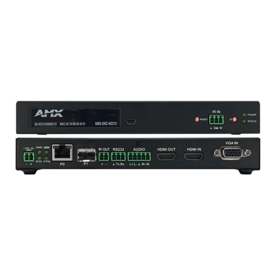
Introducing Your New N2300 Series Devices Introducing Your New N2300 Series Devices Product Overview The N2300 AV over IP Series belongs to the N-Series product family from AMX and consists of N2312 Encoders and N2322 Decoders. This series provides a flexible, feature-rich, and simple-to-deploy digital media distribution and switching solution that can be used in 4K applications with resolutions up to 4096x2160, with support for HDCP 2.2. - Page 7 Introducing Your New N2300 Series Devices 1) USB Standard-A Ports 4) Device ID Discovery Button 2) Device Reset Button 5) Power/Status Indicators 3) IR Emitter Input Connection FIG. 3 N2322 Decoder Front Panel 1) 12VDC Input (not needed with PoE) 5) IR Emitter Output Connection 2) Status Indicators 6) RS232 Connection...
- Page 8 Introducing Your New N2300 Series Devices Front and Rear Panel Descriptions (Cont.) IR OUT 2-pin terminal Phoenix connector. Provides IR output only (33 to 60 kHz; typically 39 kHz). An IR emitter is necessary (not included). RS232 3-pin terminal Phoenix connector which provides a serial control interface. Full duplex communication. Available terminal speed settings: 1200 to 115200 baud rate.
-
Page 9: Chapter 2: Installing And Configuring Your Av Equipment
Installing and Configuring Your AV Equipment Installing and Configuring Your AV Equipment This chapter provides an installation overview as well as a detailed step-by-step process for installation. If you encounter any problems, refer to the Troubleshooting section on page 56 for help. -
Page 10: Mounting Options
Installing and Configuring Your AV Equipment Mounting Options The N2300 units are available in stand-alone and card versions. The stand-alone version can be free standing, surface mounted, wall mounted, or rack mounted. All cards must be rack mounted using the N9206 Card Cage (sold separately). Surface and Wall Mounting To mount your N2300 stand-alone unit to a flat surface or wall, follow these steps: Remove the four screws from the bottom of the unit and use them to attach the mounting wings (not included in shipment -... - Page 11 Installing and Configuring Your AV Equipment FIG. 7 Rack Mounting Cards Align the thumb screw on back plate before seating card into cage. Firmly seat the card and tighten the thumb screw by hand to secure card placement. Use one of the six Phoenix connector cables (included in shipment with the Card Cage) to connect the card’s 12VDC input Phoenix connector to one of the cage’s six 12VDC outputs.
-
Page 12: Step-By-Step Installation Instructions
Installing and Configuring Your AV Equipment Step-by-Step Installation Instructions This section provides step-by-step guidance for installing and configuring equipment from the N-Series product family on your network. The steps provided here assume the following to be true: There are switches operational on the network. N-Series equipment can operate on many different brands of networking equipment. - Page 13 Installing and Configuring Your AV Equipment Double-click the wired interface to your AV network, and then click the Properties button. Scroll down in the list to the Internet Protocol Version 4 (TCP/IPv4) option. Highlight it and click the Properties button. N2312/N2322 User Manual...
- Page 14 Installing and Configuring Your AV Equipment Enable the Use the following IP address option, and enter the static IP address provided to you by your network administrator. NOTE: If the computer does not need Internet access, you can simply enter a unique 169.254.xxx.xxx IP address with a 255.255.0.0 subnet mask.
- Page 15 Installing and Configuring Your AV Equipment Once the Decoders and displays are connected and powered up, the LocalPlay screen appears on the displays. NOTE: If the LocalPlay screen does not appear, refer to the chapter Troubleshooting on page 56 for more guidance. NOTE: In order for the unit to receive PoE, it must be connected to a switch or other equipment that has a PoE PSE (Power Sourcing Equipment) port.
- Page 16 Installing and Configuring Your AV Equipment Encoders are listed across the top of the page. Decoders are listed down the left side of the page. Red Text - No video source (Encoder) or no display (Decoder). Black Text - Unit is in live play mode. Red Exclamation Point (!) - N-Able cannot communicate with device.
-
Page 17: How Ip Address Changes Affect Unit Control
Installing and Configuring Your AV Equipment FIG. 13 Changing Stream Setting Repeat these steps until all Encoders are connected to the network and configured with an appropriate Stream number. NOTE: Each Encoder’s Stream number must be unique to all other Encoders on the network. NOTE: Screen-by-screen descriptions of the web interface options are provided for your reference in the Encoder Configuration Options section on page 23... -
Page 18: Changing Ip Addresses
Installing and Configuring Your AV Equipment Changing IP Addresses There are two ways to assign new IP addresses to your N2300 units using N-Able: Option 1: Log in to each unit individually and make the changes on the Settings page. ... - Page 19 Installing and Configuring Your AV Equipment Step 5: Connecting Encoders to an Input Source Having already connected the Encoder(s) to the network and made the appropriate settings changes (as described in Step 3 Step 4), you can now connect to the appropriate AV source(s). This connection from an Encoder HDMI IN port (female) to an input source is accomplished using either an HDMI cable or DVI-I (through adapter).
-
Page 20: Switching And Scaling Options
Installing and Configuring Your AV Equipment Switching and Scaling Options N-Series Encoders and Decoders make up a true AV matrix solution. In other words, one input can go to any or all outputs. Decoders have internal scaling capabilities. Keep the following in mind: The input of an Encoder is the video and/or audio signal going into the Encoder. -
Page 21: Control Options
Installing and Configuring Your AV Equipment Control Options For the most part, once the initial setup is complete, you will be primarily managing/configuring the Decoders. To better understand, think of Encoders as radio stations and Decoders as car radios. The Encoders are supplying the streams and, using the Decoders, you can “tune in”... -
Page 22: Kvm Configuration
Installing and Configuring Your AV Equipment KVM Configuration The N2312 Encoders and N2322 Decoders are KVM-capable. By default, USB connections are disabled. Basic Setup Follow these steps for basic KVM configuration: On the N2312 Encoder, connect the USB Mini-B port to the computer to be controlled. Connect the computer’s video output to the Encoder’s HDMI IN port. -
Page 23: Chapter 3: Encoder Configuration Options
Encoder Configuration Options Encoder Configuration Options This chapter defines N2312 Encoder configuration options. For ease of navigation, it is organized to reflect the graphical user interface (GUI). From any main page in the GUI, you can access all other main pages by clicking the links in the top navigation bar. Figure 17 shows the navigation bar and provides hot links to the sections of this chapter which describe each main page. -
Page 24: Settings Page
Encoder Configuration Options Settings Page Click the Settings link at the top of any of the main web pages to access the page shown in Figure 18. This page is divided into several sections and has links to other dialog boxes for additional configuration options. Refer to the following sections for detailed descriptions: Device Settings Section on page 25 ... -
Page 25: Device Settings Section
Encoder Configuration Options Device Settings Section The Device Settings section of the Settings page is shown in Figure 19. Options are described in Table FIG. 19 Device Settings Section TABLE 1 Settings Page: Device Settings Section Option Description Notes Device Name More descriptive names in this field help you organize Enter a user-friendly name for the unit. -
Page 26: Advanced Settings
Encoder Configuration Options Advanced Settings The Advanced Settings section of the Settings page is shown in Figure 20. Options are described in Table FIG. 20 Advanced Settings TABLE 2 Settings Page: Advanced Settings Option Description Notes Settings Lock Enable to lock the Encoder IP settings and stream This does not prevent a control system from making number, preventing automated processes (from N-Able changes or a user from manually making changes. - Page 27 Encoder Configuration Options TABLE 2 Settings Page: Advanced Settings (Cont.) Option Description Notes Status Interval (secs) Determine how often (in seconds) the unit transmits status packets. Serial Master Enable Enable this device to be the server to the designated client. Serial Client Address Enter the IP address of the serial client device.
-
Page 28: Network Setup Section
Encoder Configuration Options Network Setup Section The Network Setup section of the Settings page is shown in Figure 21. Options are described in Table FIG. 21 Network Setup Section TABLE 3 Settings Page: Network Setup Section Option Description Notes IP Mode Configure the IP address mode. -
Page 29: Status Section
Encoder Configuration Options Status Section The Status section of the Settings page is shown in Figure 22. Options are described in Table FIG. 22 Status Section TABLE 4 Settings Page: Status Section Option Description Notes HDMI Status Indicates if a video source is connected to the Encoder. Input Resolution Indicates the video resolution of the currently connected source. -
Page 30: Software Section
Encoder Configuration Options Software Section The Software section of the Settings page is shown in Figure 23. Options are described in Table FIG. 23 Software Section TABLE 5 Settings Page: Software Section Option Description Displays the serial number of the N2312 Encoder. Displays the MAC address of the network interface of the N2312 Encoder. -
Page 31: Hostplay Page
Encoder Configuration Options HostPlay Page Click the HostPlay link at the top of any of the main web pages to access the page shown in Figure 25. This page allows you to upload new images to the Encoders and assign them to one of eight playlists. The designated playlist is shown on the display when no video is being transmitted or received. -
Page 32: N-Act Page
Encoder Configuration Options N-Act Page Click the N-Act link at the top of any of the main web pages to access the page shown in Figure 26. This page allows you to create command lists which are performed automatically by the unit based on power or video connection (without the use of an outside controller). -
Page 33: Serial Page
Encoder Configuration Options Serial Page Click the Serial link at the top of any of the main web pages to access the page shown in Figure 27. This page allows you to upload and execute commands used for direct control of serial devices. Commands may be saved for future use and executed later. The Serial Code menu lists all saved commands. -
Page 34: Ir Page
Encoder Configuration Options IR Page Click the IR link at the top of any of the main web pages to access the page shown in Figure 28. This page allows you to upload and execute IR Pronto codes so that other vendor’s devices can be controlled through the Encoder’s IR connector. Commands can be saved for future use and executed later. -
Page 35: Security Page
Encoder Configuration Options Security Page Click the More link at the top of any of the main web pages and select Security to access the page shown in Figure 30. This page allows you to force HTTPS connections. To successfully communicate, the Decoder must know and match the Encoder password. FIG. - Page 36 Encoder Configuration Options TABLE 11 EDID Page Options Option Description Digital EDID section Click the Read button to initially show the Encoder’s local digital EDID information. This information is being provided to the source connected to the Encoder. You can modify the default digital EDID using an EDID captured from a display connected to a Decoder. Simply copy and paste the new EDID into the Digital EDID field and click the Set Digital EDID button.
-
Page 37: Lldp Page
Encoder Configuration Options LLDP Page Click the More link at the top of any of the main web pages and select LLDP to access the page shown in 32. The LLDP page Figure displays information from the Link Layer Discover Protocol (LLDP) packet which identifies the port number and switch the device is connected to. - Page 38 Encoder Configuration Options TABLE 12 NetLinx Page Options (Cont.) Command Description Port This field should always be set to 1319. Device Number Defaults to a dynamic device number. May be set to a static range (e.g., 8000). System Number Determines which system to connect. This setting is dependent upon the Master Mode selected (see above). •...
-
Page 39: Chapter 4: Decoder Configuration Options
Decoder Configuration Options Decoder Configuration Options This chapter defines N2322 Decoder configuration options. For ease of navigation, it is organized to reflect the graphical user interface (GUI). As explained previously in the Encoder Conf iguration Options section on page 23, you can access the GUI main pages by clicking the links in the top navigation bar. -
Page 40: Settings Page
Decoder Configuration Options Settings Page Click the Settings link at the top of any of the main web pages to access the page shown in Figure 35. This page is divided into several sections and also has links to other dialog boxes for additional configuration options. Refer to the following sections for detailed descriptions: Device Settings Section on page 41 ... -
Page 41: Device Settings Section
Decoder Configuration Options Device Settings Section The Device Settings section of the Settings page is shown in Figure 36. Options are described in Table FIG. 36 Device Settings Section TABLE 13 Settings Page: Device Settings Section Option Description Notes Device Name Enter a user-friendly name for the unit. -
Page 42: Advanced Settings
Decoder Configuration Options Advanced Settings The Advanced Settings section of the Settings page is shown in Figure 37. Options are described in Table FIG. 37 Advanced Settings TABLE 14 Settings Page: Advanced Settings Option Description Notes Settings Lock Enable to lock the Decoder IP settings and stream This does not prevent a control system from making number, preventing automated processes (from N-Able changes or a user from manually making changes. - Page 43 Decoder Configuration Options TABLE 14 Settings Page: Advanced Settings (Cont.) Option Description Notes HDMI Off On Stream Select to disable the video output drive when the video Loss stream is not available. HDMI Enable Select to enable output video. Gratuitous ARP Enable the Decoder to send a periodic Address Resolution Protocol (ARP) packet to the network.
- Page 44 Decoder Configuration Options TABLE 14 Settings Page: Advanced Settings (Cont.) Option Description Notes Disable P1 Once disabled, anything connected to the P1 port will Completely disables the P1 port for all traffic. no longer be available on the network. Save button Click to save settings made in this portion of the Advanced section.
-
Page 45: Network Setup Section
Decoder Configuration Options Network Setup Section The Network Setup section of the Settings page is shown in Figure 38. Options are described in Table FIG. 38 Network Setup Section TABLE 15 Settings Page: Network Setup Section Option Description Notes IP Mode Configure the IP address mode. -
Page 46: Status Section
Decoder Configuration Options Status Section The Status section of the Settings page is shown in Figure 39. Options are described in Table FIG. 39 Status Section TABLE 16 Settings Page: Status Section Option Description Notes HDMI Status Indicates if a monitor is connected. Input Resolution Indicates the video resolution of the incoming video source. -
Page 47: Software Section
Decoder Configuration Options Software Section The Software section of the Settings page is shown in Figure 40. Options are described in Table FIG. 40 Software Section TABLE 17 Settings Page: Software Section Option Description Displays the serial number of the N2322 Decoder. Displays the MAC address of the network interface of the N2322 Decoder. -
Page 48: Wall Page
Decoder Configuration Options Wall Page Click the Wall link at the top of any of the main web pages to access the page shown in Figure 42. This page allows you to create video walls made up of the output from multiple Decoders. See Table 20 for option descriptions. -
Page 49: Localplay Page
Decoder Configuration Options LocalPlay Page Click the LocalPlay link at the top of any of the main web pages to access the screen shown in Figure 43. This page allows you to upload new images to the Decoders and assign them to one of eight playlists. The designated playlist is shown on the display when no video is being transmitted or received. -
Page 50: N-Act Page
Decoder Configuration Options N-Act Page Click the N-Act link at the top of any of the main web pages to access the page shown in Figure 44. This page allows you to create command lists which are performed automatically by the unit based on power or video connection (without the use of an outside controller). -
Page 51: Serial Page
Decoder Configuration Options Serial Page Click the Serial link at the top of any of the main web pages to access the page shown in Figure 45. This page allows you to upload and execute commands used for direct control of serial devices. Commands may be saved for future use and executed later. The Serial Code menu lists all saved commands. -
Page 52: Ir Page
Decoder Configuration Options IR Page Click the IR link at the top of any of the main web pages to access the page shown in Figure 46. This page allows you to upload and execute IR Pronto codes so that other vendor’s devices can be controlled through the Decoder’s IR connector. Commands can be saved for future use and executed later. -
Page 53: Security Page
Decoder Configuration Options Security Page Click the More link at the top of any of the main web pages and select Security to access the page shown in Figure 48. This page allows you to force HTTPS connections. To successfully communicate, the Decoder must know and match the Encoder password. FIG. -
Page 54: Lldp Page
Decoder Configuration Options LLDP Page Click the More link at the top of any of the main web pages and select LLDP to access the page shown in 50. The LLDP page Figure displays information from the Link Layer Discover Protocol (LLDP) packet which identifies the port number and switch the device is connected to. - Page 55 Decoder Configuration Options TABLE 26 NetLinx Page Options (Cont.) Command Description Port This field should always be set to 1319. Device Number Defaults to a dynamic device number. May be set to a static range (e.g., 8000). System Number Determines which system to connect. This setting is dependent upon the Master Mode selected (see above). •...
-
Page 56: Chapter 5: Troubleshooting
This chapter contains possible solutions to some common issues. Should you encounter any problems not covered by these guidelines, please contact technical support via email (svsisupport@harman.com) or call +1 (844) 776-4899. You can also visit our support webpage at amx.com/support. -
Page 57: Series Default Local/Host Play Troubleshooting Screens
Troubleshooting Series Default Local/Host Play Troubleshooting Screens This section shows and defines the status screens displayed by N2300 Series devices. FIG. 52 Host Play Screen Displayed when Decoder..and Encoder..Notes • is set to view an Encoder stream on •... - Page 58 Troubleshooting FIG. 54 Restricted Content Not Supported Screen Displayed when Decoder..and Encoder..Notes • is receiving a stream from an • is transmitting HDCP-protected Once the Decoder detects that the monitor is not Encoder content to the Decoder HDCP compliant, this screen is displayed. If you suspect that this message was displayed in error, •...
-
Page 59: Appendix A: Netlinx Control
Appendix A: NetLinx Control Appendix A: NetLinx Control Introduction NetLinx Studio is commonly used by system programmers to streamline the integration, programming, organization, and support of their AMX equipment. As the cornerstone of AMX's system design software tools, NetLinx Studio offers programmers the most flexible application capable of generating the most sophisticated code possible. -
Page 60: Batch Configurations Using N-Able
Appendix A: NetLinx Control NetLinx Configuration Options (Cont.) TABLE 27 Command Description System Number Determines which system to connect. This setting is dependent upon the Master Mode selected (see above). • If Master Mode is set to Auto, the System Number is set and the system discovers the Central Controller’s IP address. -
Page 61: Native Commands Port 1
Encoder/Decoder Commands Encoder/Decoder Commands The following section provides information on native, string, IR, and serial commands for N-Series Encoders and Decoders as related to NetLinx management. Commands are issued on the following ports: • Port 1: Native and String Commands •... - Page 62 Encoder/Decoder Commands Native Commands Port 1 (Cont.) Command Description IMPORTANT: This command must be sent to D:P:S port 1. LOCAL_PLAY <Playlist index> Enable Local Play on Decoders or Host Play on Syntax: Encoders using the Playlist number. SEND_COMMAND <DEV>, ’LOCAL_PLAY index’ Variables: Playlist index = Which Default Playlist index to enable.
-
Page 63: Ir/Serial Send Commands Port 3
Encoder/Decoder Commands Native Commands Port 1 (Cont.) Command Description ?LOCAL_PLAY Syntax: Request the Local Play/Host Play Playlist SEND_COMMAND <DEV>, ’?LOCAL_PLAY’ Examples: number. SEND_COMMAND 5002:1:0, ’?LOCAL_PLAY’ Command Response: ’LOCAL_PLAY-1’ ?USB_HID_SERVICE Syntax: Request the status of the USB. SEND_COMMAND <DEV>, ’?USB_HID_SERVICE’ Examples: SEND_COMMAND 5002:1:0, ’?USB_HID_SERVICE’... -
Page 64: Ir Port 2
Encoder/Decoder Commands IR Port 2 Using the NetLinx Studio application, download the appropriate IR file to the N-Series device to use the appropriate channels. Port 2 is used to send IR commands. Some tuning of the NetLinx Pulse Time, IR Command Holdoff, and IR Repeat Holdoff on the N-Series device may be required. -
Page 65: Appendix B: Minimum Network Requirements
TCN flood protocol will cause unnecessary backplane and bandwidth usage when adding or removing a device on the network. This can cause stream interruptions as the flooding sweeps through the network. Should you encounter any problems not covered by these guidelines, please contact technical support via email (svsisupport@harman.com) or call +1 (844) 776-4899. N2312/N2322 User Manual... - Page 66 © 2020 Harman. All rights reserved. AMX, AV FOR AN IT WORLD, and HARMAN, and their respective logos are registered trademarks of HARMAN. Last Revised: Oracle, Java and any other company or brand name referenced may be trademarks/registered trademarks of their respective companies.
Need help?
Do you have a question about the AMX NMX-ENC-N2312 and is the answer not in the manual?
Questions and answers