
Related Manuals for Harman AMX NMX-ENC-N2412A


Summary of Contents for Harman AMX NMX-ENC-N2412A
- Page 1 INSTRUCTION MANUAL N2400 SERIES N2412A ENCODERS/N2422A, N2424A DECODERS DIGITAL MEDIA DISTRIBUTION & SWITCHING SOLUTION NM X- ENC - N241 2A, NM X- DEC - N2422A, NM X- DEC - N2424A...
- Page 2 IMPORTANT SAFETY INSTRUCTIONS READ these instructions. KEEP these instructions. HEED all warnings. FOLLOW all instructions. DO NOT use this apparatus near water. CLEAN ONLY with dry cloth. DO NOT block any ventilation openings. Install in accordance with the manufacturer's instructions. DO NOT install near any heat sources such as radiators, heat registers, stoves, or other apparatus (including amplifiers) that produce heat.
- Page 3 ESD WARNING To avoid ESD (Electrostatic Discharge) damage to sensitive components, make sure you are properly grounded before touching any internal materials. When working with any equipment manufactured with electronic devices, proper ESD grounding procedures must be followed to make sure people, products, and tools are as free of static charges as possible.
-
Page 4: Table Of Contents
Table of Contents Chapter 1: Introducing Your New N2400 Series Devices ............6 Product Overview ..........................6 Hardware Overview ........................... 6 Chapter 2: Installing and Configuring Your AV Equipment ..........9 Installation Overview .......................... 9 Mounting Options..........................10 Surface and Wall Mounting ......................10 Rack Mounting .......................... - Page 5 Logs Page ............................43 LLDP Page .............................. 44 NetLinx Page ............................ 44 AES67 Page ............................45 Chapter 4: Decoder Configuration Options ................ 46 Settings Page ........................... 47 Decoder Setup Section ........................48 Advanced Settings ..........................50 RS232 Settings ..........................52 Effects Settings ..........................
-
Page 6: Chapter 1: Introducing Your New N2400 Series Devices
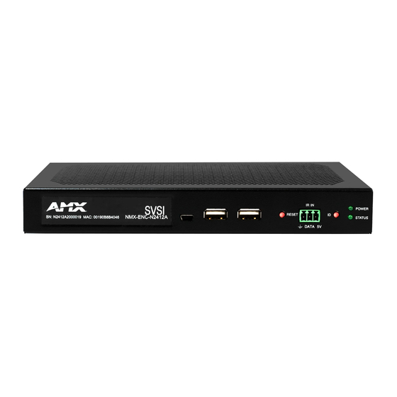
Introducing Your New N2400 Series Devices Chapter 1: Introducing Your New N2400 Series Devices Product Overview The N2400 AV over IP Series belongs to the N-Series product family from AMX. This series provides a flexible, feature-rich, and simple-to-deploy digital media distribution and switching solution satisfying the most demanding applications. N-Series video over IP Encoders are used to encode and distribute sources of almost any format onto an existing IP network, making that stream available to any endpoint in the facility. - Page 7 Introducing Your New N2400 Series Devices 1) USB Mini-B Port 5) IR Emitter Input Connection 2) USB Type A Port 6) Device ID Discovery Button 3) USB Type A Port 7) Power/Status Indicators 4) Device Reset Button FIG. 3 N2422A Decoder Front Panel 1) 12VDC Input (not needed with PoE+) 5) IR Emitter Output Connection 2) Status Indicators...
- Page 8 Introducing Your New N2400 Series Devices Front and Rear Panel Descriptions Front Panel USB Mini-B port For KVM support. Connects the Encoder to the computer to be controlled. USB Standard-A port For KVM support. Connects the Decoder to keyboard and/or mouse. (x2) RESET button Recessed pushbutton.
-
Page 9: Chapter 2: Installing And Configuring Your Av Equipment
Installing and Configuring Your AV Equipment Chapter 2: Installing and Configuring Your AV Equipment This chapter provides an installation overview as well as a detailed step-by-step process for installation. If you encounter any problems, refer to the Troubleshooting section on page 67 for help. -
Page 10: Mounting Options
Installing and Configuring Your AV Equipment Mounting Options The N2400 units are available in stand-alone and the N2412A-C encoder card version. The stand-alone version can be free standing, surface mounted, wall mounted, or rack mounted. All cards must be rack mounted using the N9206 Card Cage (sold separately). - Page 11 Installing and Configuring Your AV Equipment FIG. 9 Rack Mounting Cards Align the thumb screw on back plate before seating card into cage. Firmly seat the card and tighten the thumb screw by hand to secure card placement. Use one of the six Phoenix connector cables (included in shipment with the Card Cage) to connect the card’s 12VDC input Phoenix connector to one of the cage’s six 12VDC outputs.
-
Page 12: Step-By-Step Installation Instructions
Installing and Configuring Your AV Equipment Step-by-Step Installation Instructions This section provides step-by-step guidance for installing and configuring equipment from the N-Series product family on your network. The steps provided here assume the following to be true: There are switches operational on the network. N-Series equipment can operate on many different brands of networking equipment. - Page 13 Installing and Configuring Your AV Equipment Double-click the wired interface to your AV network, and then click the Properties button. Scroll down in the list to the Internet Protocol Version 4 (TCP/IPv4) option. Highlight it and click the Properties button. N2412A/N2422A User Manual...
- Page 14 Installing and Configuring Your AV Equipment Enable the Use the following IP address option, and enter the static IP address provided to you by your network administrator. NOTE: If the computer does not need Internet access, you can simply enter a unique 169.254.xxx.xxx IP address with a 255.255.0.0 subnet mask.
- Page 15 Installing and Configuring Your AV Equipment NOTE: If the LocalPlay screen does not appear, refer to the chapter Troubleshooting on page 67 for more guidance. NOTE: In order for the unit to receive PoE+, it must be connected to a switch or other equipment that has a PoE+ PSE (Power Sourcing Equipment) port.
- Page 16 Installing and Configuring Your AV Equipment Encoders are listed across the top of the page. Decoders are listed down the left side of the page. Red Text - No video source (Encoder) or no display (Decoder). Black Text - Unit is in live play mode. Red Exclamation Point (!) - N-Able cannot communicate with device.
-
Page 17: How Ip Address Changes Affect Unit Control
Installing and Configuring Your AV Equipment FIG. 15 Changing Stream Setting Repeat these steps until all Encoders are connected to the network and configured with an appropriate Stream number. NOTE: Each Encoder’s Stream number must be unique to all other Encoders on the network. NOTE: Screen-by-screen descriptions of the web interface options are provided for your reference in the Encoder Configuration Options section on page 23 and the Decoder Configuration Options section on page 44. -
Page 18: Changing Ip Addresses
Installing and Configuring Your AV Equipment Changing IP Addresses There are two ways to assign new IP addresses to your N2400 units using N-Able: Option 1: Log in to each unit individually and make the changes on the Settings page. ... - Page 19 Installing and Configuring Your AV Equipment Step 5: Connecting Encoders to an Input Source Having already connected the Encoder(s) to the network and made the appropriate settings changes (as described in Step 3 Step 4), you can now connect to the appropriate AV source(s). This connection from an Encoder HDMI IN port (female) to an input source is accomplished using either an HDMI cable or DVI-I (through adapter).
-
Page 20: Switching And Scaling Options
Installing and Configuring Your AV Equipment Switching and Scaling Options N-Series Encoders and Decoders make up a true AV matrix solution. In other words, one input can go to any or all outputs. Decoders have internal scaling capabilities. Keep the following in mind: The input of an Encoder is the video and/or audio signal going into the Encoder. -
Page 21: Control Options
Installing and Configuring Your AV Equipment Control Options For the most part, once the initial setup is complete, you will be primarily managing/configuring the Decoders. To better understand, think of Encoders as radio stations and Decoders as car radios. The Encoders are supplying the streams and, using the Decoders, you can “tune in”... -
Page 22: Kvm Configuration
Installing and Configuring Your AV Equipment KVM Configuration The N2412A Encoders, N2422A and N2424A Decoders are KVM-capable. By default, USB connections are disabled. Basic Setup Follow these steps for basic KVM configuration: On the N2412A Encoder, connect the USB Mini-B port to the computer to be controlled. Connect the computer’s video output to the Encoder’s HDMI IN port. -
Page 23: Chapter 3: Encoder Configuration Options
Encoder Configuration Options Chapter 3: Encoder Configuration Options This chapter defines N2412A Encoder configuration options. For ease of navigation, it is organized to reflect the graphical user interface (GUI). From any main page in the GUI, you can access all other main pages by clicking the links in the top navigation bar. Figure 19 shows the navigation bar and provides hot links to the sections of this chapter which describe each main page. -
Page 24: Settings Page
Encoder Configuration Options Settings Page Click the Settings link at the top of any of the main web pages to access the page shown in Figure 20. This page is divided into several sections and also has links to other dialog boxes for additional configuration options. Refer to the following sections for detailed descriptions: Encoder Setup Section on page 25 ... -
Page 25: Encoder Setup Section
Encoder Configuration Options Encoder Setup Section The Encoder Setup section of the Settings page is shown in Figure 21. Options are described in Table FIG. 21 Encoder Setup Section TABLE 1 Settings Page: Encoder Setup Section Option Description Notes Enter a user-friendly name for the unit. More descriptive names in this field help you organize Device Name and manage the N-Series system efficiently. - Page 26 Encoder Configuration Options TABLE 1 Settings Page: Encoder Setup Section (Cont.) Option Description Notes Image Quality Adjust the compression level of the image. The further to the left on the slider, the more compression which will display as pixelization of the image. Enable to mute video by outputting solid black.
-
Page 27: Advanced Settings
Encoder Configuration Options Advanced Settings The section of the Settings page shown in Figure 22 is displayed when you click the Advanced Settings link. Options are described in Table FIG. 22 Advanced Settings N2412A/N2422A User Manual... - Page 28 Encoder Configuration Options TABLE 2 Settings Page: Advanced Settings Option Description Notes Settings Lock Enable to lock the Encoder IP Settings If enabled, the user must disable the Settings Lock before making any changes. Input Level Gain Left/ Select a PRE-ENCODE cut in the audio signal. This can help prevent distortion of the audio when the source is providing audio that is too loud/clipping.
-
Page 29: Rs232 Settings
Encoder Configuration Options TABLE 2 Settings Page: Advanced Settings (Cont.) Option Description Notes IR Repeat Holdoff Set the repeat delay between IR commands. The default This is the amount of time before a new command is setting is 90 ms. sent. -
Page 30: Effects Settings
Encoder Configuration Options Effects Settings The section of the Settings page shown in Figure 24 is displayed when you click the Effects Settings link. Options are described Table FIG. 24 Effects Settings TABLE 4 Settings Page: Effects Settings Option Description Border Enable Enable to add a border around the video. -
Page 31: Network Setup Section
Encoder Configuration Options Network Setup Section The Network Setup section of the Settings page is shown in Figure 23. Options are described in Table FIG. 23 Network Setup Section TABLE 5 Settings Page: Network Setup Settings Option Description Notes Configure the IP address mode. When set to AUTO IP, DHCP is the default setting. - Page 32 Encoder Configuration Options TABLE 6 Settings Page: Status Section Option Description Notes Indicates if data is being sent to the HDMI port. HDMI Status Indicates if data is being sent to the VGA port. VGA Status Indicates the video resolution of the currently Source Resolution connected source.
-
Page 33: Change Password Section
Encoder Configuration Options Change Password Section To change the N2412A Encoder interface password, enter the current password in the field labeled Old Password, and enter a new password in the New Password and Confirm Password fields. Click Change PW to accept the new password. FIG. -
Page 34: Hdmi Pass Thru Settings
Encoder Configuration Options TABLE 8 Settings Page: Software Section Option Description Displays the model number of the N2400 Encoder. Model Serial Displays the serial number of the N2400 Encoder. MAC Address Displays the MAC address of the network interface of the N2400 Encoder. Displays the date code for the currently running version of the N2400 Encoder internal firmware. -
Page 35: Hostplay Page
Encoder Configuration Options HostPlay Page Click the HostPlay link at the top of any of the main web pages to access the page shown in Figure 31. This page allows you to upload new images to the Encoders and configure the image playlists. The playlist will be shown on the display when no video is being transmitted or received. - Page 36 Encoder Configuration Options TABLE 10 HostPlay Page Options (Cont.) Option Description Customize the background color (used behind HostPlay images that do not take up the entire screen). Fill Choose an aspect ratio for display. The Output Mode for the playlist and the loaded image (Scale setting when Scale loaded) need to match.
-
Page 37: N-Act Page
Encoder Configuration Options N-Act Page Click the N-Act link at the top of any of the main web pages to access the page shown in Figure 33. This page allows you to create command lists which are performed automatically by the unit based on power or video connection (without the use of an outside controller). -
Page 38: Serial Page
Encoder Configuration Options Serial Page Click the Serial link at the top of any of the main web pages to access the page shown in Figure 34. This page allows you to upload and execute commands used for direct control of serial devices. Commands may be saved for future use and executed later. The Serial Code menu lists all saved commands. -
Page 39: Security Page
Encoder Configuration Options Security Page Click the Security link at the top of any of the main web pages to access the page shown in Figure 35. This page allows you to customize the security settings on your unit. See Table 14 for option descriptions. - Page 40 Encoder Configuration Options TABLE 14 Security Page Options Option Description General Security Force HTTPS Enable to force web page accesses to always be HTTPS. Connection Change Stream Set the default password for stream encryption. To successfully communicate, the Decoder and Encoder Encryption Password passwords must match.
-
Page 41: Kvm Page
Encoder Configuration Options KVM Page Click the KVM link at the top of any of the main web pages to access the N-Series KVM page. You must check the USB Enable box at the top to see the page shown in Figure 34. -
Page 42: Edid Page
Encoder Configuration Options EDID Page Click the EDID link at the top of any of the main web pages to access the page shown in Figure 37. Every display has stored information that it communicates to the output device. This page allows you to view that information. Options are described in Table 16. -
Page 43: Logs Page
Encoder Configuration Options TABLE 16 EDID Page Options (Cont.) Option Description Set EDID to Pass-thru Set the EDID to the pass-thru EDID of the connected display to HDMI OUT. For Digital, choose a standard EDID from the drop-down menu and click Reset EDID to apply. For Analog, no Reset EDID selection is necessary. -
Page 44: Lldp Page
Encoder Configuration Options LLDP Page Click the LLDP link at the top of any of the main web pages to access the page shown in Figure 39. The LLDP page displays information from the Link Layer Discover Protocol (LLDP) packet which identifies the port number and switch the device is connected to. -
Page 45: Aes67 Page
Encoder Configuration Options TABLE 17 NetLinx Page Options (Cont.) Command Description This field should always be set to 1319. Port Device Number This is the device number that is assigned in the Netlinx code as part of the Device:Port:System(D:P:S) System Number Determines which system to connect. -
Page 46: Chapter 4: Decoder Configuration Options
Decoder Configuration Options Chapter 4: Decoder Configuration Options This chapter defines the N2422A and the N2424A Decoder configuration options. For ease of navigation, it is organized to reflect the graphical user interface (GUI). As explained previously in the Encoder Configuration Options section on page 23, you can access the GUI main pages by clicking the links in the top navigation bar. -
Page 47: Settings Page
Decoder Configuration Options Settings Page Click the Settings link at the top of any of the main web pages to access the page shown in Figure 43. This page is divided into several sections and also has links to other dialog boxes for additional configuration options. Refer to the following sections for detailed descriptions: Decoder Setup Section on page 46 ... -
Page 48: Decoder Setup Section
Decoder Configuration Options Decoder Setup Section The Decoder Setup section of the Settings page is shown in Figure 44. Options are described in Table FIG. 44 Decoder Setup Section TABLE 19 Settings Page: Decoder Setup Section Option Description Notes Device Name Enter a user-friendly name for the unit. - Page 49 Decoder Configuration Options TABLE 19 Settings Page: Decoder Setup Section (Cont.) Option Description Notes Enable to mute video by outputting solid black. Video Mute Enable to mute output audio Audio Mute This slider controls the output gain on the analog audio Lineout Volume output.
-
Page 50: Advanced Settings
Decoder Configuration Options Advanced Settings The section of the Settings page shown in Figure 45 is displayed when you click the Advanced Settings link. Options are described in Table FIG. 45 Advanced Settings TABLE 20 Settings Page: Advanced Settings Option Description Notes Settings Lock... - Page 51 Decoder Configuration Options TABLE 20 Settings Page: Advanced Settings (Cont.) Option Description Notes Unsolicited Status Enable the Decoder to send a periodic status packet to the Send Status Address described below. Send Status Address When Unsolicited Status is enabled, the Decoder sends a periodic status packet to the IP address specified here.
-
Page 52: Rs232 Settings
Decoder Configuration Options RS232 Settings The section of the Settings page shown in Figure 46 is displayed when you click the RS232 Settings link. Options are described in Table FIG. 46 RS232 Settings TABLE 21 Settings Page: RS232 Settings Option Description RS232 Baud Rate Select the appropriate baud rate for the RS232 serial interface. -
Page 53: Network Setup Section
Decoder Configuration Options Network Setup Section The Network Setup section of the Settings page is shown in Figure 48. Options are described in Table FIG. 48 Network Setup Section TABLE 23 Settings Page: Network Setup Settings Option Description Notes Configure the IP address mode. When set to AUTO IP, DHCP is the default setting. - Page 54 Decoder Configuration Options TABLE 24 Settings Page: Status Section Option Description Notes Indicates if video is connected to the Decoder. HDMI Status Indicates the video resolution of the incoming video Source Resolution source. Port 50001 Source IP Shows the IP address of the currently connected device Port 50001 can only accept a single external or displays Disconnected if no connection exists.
-
Page 55: Change Password Section
Decoder Configuration Options Change Password Section To change the N2422A Decoder interface password, enter the current password in the field labeled Old Password, and enter a new password in the New Password and Confirm Password fields. Click Change PW to accept the new password. FIG. -
Page 56: Audio Downmixer Settings
Decoder Configuration Options TABLE 26 Settings Page: Software Section Option Description Displays the model number of the N2400 Decoder. Model Displays the serial number of the N2400 Decoder. Serial MAC Address Displays the MAC address of the network interface of the N2400 Decoder. Firmware Version Displays the date code for the currently running version of the N2400 Decoder internal firmware. -
Page 57: Crop/Pan/Zoom Page
Decoder Configuration Options Crop/Pan/Zoom Page Click the Crop/Pan/Zoom link at the top of any of the main web pages to access the page shown in Figure 54. This page allows you to customize the viewable portion of the input. See Table 29 for option descriptions. -
Page 58: Localplay Page
Decoder Configuration Options LocalPlay Page Click the LocalPlay link at the top of any of the main web pages to access the screen shown in Figure 55. This page allows you to upload new images to the Decoders and configure the image playlists. The playlist will be shown on the display when no video is being transmitted or received. - Page 59 Decoder Configuration Options TABLE 30 LocalPlay Page Options (Cont.) Option Description Click to add the selected slide to the current playlist (shown on the left side of the screen). Add Slide(s) button Delete the selected image file from the playlist. Delete Image(s) IR Page Click the IR link at the top of any of the main web pages to access the page shown in...
-
Page 60: N-Act Page
Decoder Configuration Options N-Act Page Click the N-Act link at the top of any of the main web pages to access the page shown in Figure 57. This page allows you to create command lists which are performed automatically by the unit based on power or video connection (without the use of an outside controller). -
Page 61: Serial Page
Decoder Configuration Options Serial Page Click the Serial link at the top of any of the main web pages to access the page shown in Figure 58. This page allows you to upload and execute commands used for direct control of serial devices. Commands may be saved for future use and executed later. The Serial Code menu lists all saved commands. -
Page 62: Security Page
Decoder Configuration Options Security Page Click the Security link at the top of any of the main web pages to access the page shown in Figure 59. This page allows you to customize the security settings on your unit. See Table 34 for option descriptions. - Page 63 Decoder Configuration Options TABLE 34 Security Page Options Option Description General Security Force HTTPS Enable to force web page accesses to always be HTTPS. Connection Change Stream Set the default password for stream encryption. To successfully communicate, the Decoder and Encoder Encryption Password passwords must match.
-
Page 64: Kvm Page
Decoder Configuration Options KVM Page Click the KVM link at the top of any of the main web pages to access the N-Series KVM page. You must check the USB Enable box at the top to see the page shown in Figure 60. -
Page 65: Edid Page
Decoder Configuration Options TABLE 35 KVM Page Options (Cont.) Option Description KVM Encoders View/edit the list of Encoders associated with this Decoder. Here you can Add/Overwrite Encoders to the list by Name or IP Address as well as assign Passwords, and Hotkey Numbers (explained below). You can also end the Decoder/Encoder association by clicking the Remove Encoder button. -
Page 66: Logs Page
Decoder Configuration Options TABLE 36 EDID Page Options (Cont.) Option Description Click to translate the EDID currently displayed on the left to the operating parameters list on the right. Decode button After making any changes to the operating parameters list on the right, click this button to update the EDID Encode button information on the left. -
Page 67: Lldp Page
Decoder Configuration Options LLDP Page Click the LLDP link at the top of any of the main web pages to access the page shown in Figure 63. The LLDP page displays information from the Link Layer Discover Protocol (LLDP) packet which identifies the port number and switch the device is connected to. -
Page 68: Aes67 Page
Decoder Configuration Options TABLE 37 NetLinx Page Options (Cont.) Command Description This field should always be set to 1319. Port Device Number This is the device number that is assigned in the NetLinx code as part of the Device:Port:System(D:P:S) System Number Determines which system to connect. -
Page 69: Chapter 5: Troubleshooting
Troubleshooting Chapter 5: Troubleshooting This chapter contains possible solutions to some common issues. Issues Suggestions • Verify Decoder is assigned to view a valid stream (of an active Encoder). LocalPlay screen displays instead of the stream from the Encoder. • Verify Decoder is currently in Live play mode (its name will display in black text on the Video Matrix page). -
Page 70: Series Default Local/Host Play Troubleshooting Screens
Troubleshooting Series Default Local/Host Play Troubleshooting Screens This section shows and defines the status screens displayed by N2400 Series devices. FIG. 66 Host Play Screen Displayed when Decoder..and Encoder..Notes • is set to view an Encoder stream on •... - Page 71 Troubleshooting FIG. 68 Unsupported Input Resolution Screen Displayed when Decoder..and Encoder..Notes • is set to view an Encoder stream on • is being fed a video resolution that This screen can be useful to show you that the the network it does not support Decoder is receiving the stream from the...
- Page 72 Troubleshooting FIG. 70 Video Encrypted Screen Displayed when Decoder..Notes • is receiving a stream from an Encoder it cannot decrypt Make sure the Decoder has the correct password for decrypting the stream. To reset the password, go to the Security page on both the Encoder and Decoder and click the Reset button.
-
Page 73: Appendix A: Netlinx Control
Appendix A: NetLinx Control Appendix A: NetLinx Control Introduction NetLinx Studio is a Microsoft Windows program commonly used by system programmers to streamline the integration, programming, organization, and support of AMX equipment. As the cornerstone of AMX's system design software tools, NetLinx Studio offers programmers the most flexible application capable of generating the most sophisticated code possible. -
Page 74: Batch Configurations Using N-Able
Appendix A: NetLinx Control NetLinx Configuration Options (Cont.) TABLE 39 Command Description Username for the Central Controller. Username Password for the Central Controller. Password Save settings made on this page. Save Batch Configurations Using N-Able One of the many benefits of using N-Able control is batch configuration. This is especially useful in larger deployments. Instead of using the individual unit web pages (discussed in the previous section), simply open N-Able and select Tools >... -
Page 75: Encoder/Decoder Commands
Appendix A: NetLinx Control Encoder/Decoder Commands The following section provides information on native, string, IR, and serial commands for N-Series Encoders and Decoders as related to NetLinx management. Commands are issued on the following ports: • Port 1: Native and String Commands •... - Page 76 Appendix A: NetLinx Control Native Commands Port 1 (Cont.) Command Description IMPORTANT: This command must be sent to D:P:S port 1. LOCAL_PLAY <Playlist index> Enable Local Play on Decoders or Host Play on Syntax: Encoders using the Playlist number. SEND_COMMAND <DEV>, ’LOCAL_PLAY index’ Variables: Playlist index = Which Default Playlist index to enable.
-
Page 77: Ir/Serial Send Commands Port 3
Appendix A: NetLinx Control Native Commands Port 1 (Cont.) Command Description ?LOCAL_PLAY Syntax: Request the Local Play/Host Play Playlist SEND_COMMAND <DEV>, ’?LOCAL_PLAY’ number. Examples: SEND_COMMAND 5002:1:0, ’?LOCAL_PLAY’ Command Response: ’LOCAL_PLAY-1’ ?USB_HID_SERVICE Syntax: Request the status of the USB. SEND_COMMAND <DEV>, ’?USB_HID_SERVICE’ Examples: SEND_COMMAND 5002:1:0, ’?USB_HID_SERVICE’... -
Page 78: Ir Port 2
Appendix A: NetLinx Control IR Port 2 Using the NetLinx Studio application, download the appropriate IR file to the N-Series device to use the appropriate channels. Port 2 is used to send IR commands. Some tuning of the NetLinx Pulse Time, IR Command Holdoff, and IR Repeat Holdoff on the N-Series device may be required. -
Page 79: Appendix B: Minimum Network Requirements
Appendix B: Minimum Network Requirements Appendix B: Minimum Network Requirements As you look into an N-Series solution and try to decide what type of network topology and infrastructure will be best suited for your application, there are some minimum network requirements that must be considered when choosing the hardware to deploy a Networked AV system. - Page 80 VLAN as the N-Series devices. Command Example: NO IP IGMP SNOOPING TCN FLOOD © 2020 Harman. All rights reserved. AMX, AV FOR AN IT WORLD, and HARMAN, and their respective logos are registered trademarks of HARMAN. Last Revised: Oracle, Java and any other company or brand name referenced may be trademarks/registered trademarks of their respective companies.
Need help?
Do you have a question about the AMX NMX-ENC-N2412A and is the answer not in the manual?
Questions and answers