
Subscribe to Our Youtube Channel
Related Manuals for Harman AMX N2600 Series


Summary of Contents for Harman AMX N2600 Series
- Page 1 INSTRUCTION MANUAL N2600 SERIES NMX-ENC-N2615-WP WALLPLATE ENCODERS/NMX- DEC-N2625-WP WALLPLATE DECODERS NMX-ENC-N2615-WP-NA,NMX-DEC-N2625-WP-NA NMX-ENC-N2615-WP-EK, NMX-DEC-N2625-WP-EK...
- Page 2 IMPORTANT SAFETY INSTRUCTIONS READ these instructions. KEEP these instructions. HEED all warnings. FOLLOW all instructions. DO NOT use this apparatus near water. CLEAN ONLY with dry cloth. DO NOT block any ventilation openings. Install in accordance with the manufacturer's instructions. DO NOT install near any heat sources such as radiators, heat registers, stoves, or other apparatus (including amplifiers) that produce heat.
- Page 3 ESD WARNING To avoid ESD (Electrostatic Discharge) damage to sensitive components, make sure you are properly grounded before touching any internal materials. WARNING: This product is intended to be operated ONLY from the voltages listed on the back panel or the recommended, or included, power supply of the product.
-
Page 4: Table Of Contents
Table of Contents Introducing Your New N2600 Series Devices ..........................7 Product Overview ......................................7 Hardware Overview ......................................7 Installing and Configuring Your AV Equipment .......................... 10 Installation Overview ...................................... 10 Step-by-Step Installation Instructions .................................. 11 Step 1: Setting Up Your Host Computer ................................. 11 Step 2: Connecting Decoders to the Network ................................. - Page 5 Security Page ........................................39 Web Page Section – General Setup ..................................40 Security Certificates Section – General Setup ................................41 User Security Details Section – Users Setup ................................42 LDAP Section – LDAP Setup ....................................43 Control Page ........................................44 USB Setting –...
- Page 6 Debug Log – Log ........................................ 85 Link Layer Discovery Protocol (LLDP) – Status ................................86 Status – Status ........................................87 Current Source – Status ...................................... 88 Software – Status ......................................89 Troubleshooting ................................90 Series Default Local/Host Play Troubleshooting Screens............................91 Appendix B: Minimum Network Requirements ........................
-
Page 7: Introducing Your New N2600 Series Devices
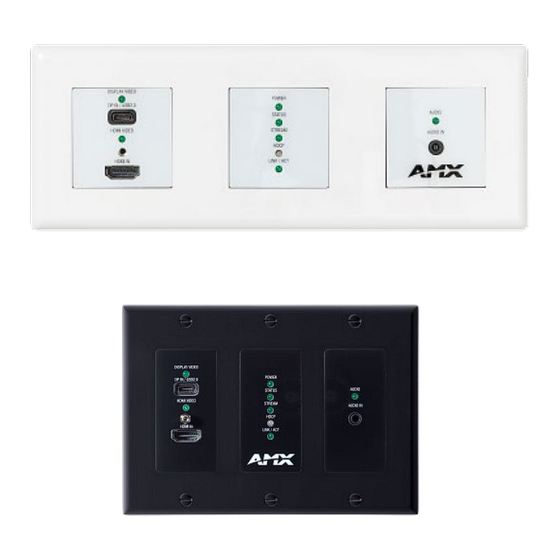
Introducing Your New N2600 Series Devices Introducing Your New N2600 Series Devices Product Overview The N2600 AV over IP Series belongs to the N-Series product family from AMX and consists of N2612 Encoders, N2622 Decoders, N2615 Wallplate Encoders and N2625 Wallplate Decoders. This series provides a flexible, feature-rich, and simple-to- deploy digital media distribution and switching solution that can be used in 4K applications with resolutions up to 4096x2160, with support for HDCP 2.2. - Page 8 Introducing Your New N2600 Series Devices 1) Analog Audio Out 6) USB-A HID Connector 2) HDMI Out 7) USB-A, USB 2.0 or HID 3) Device ID Discovery Button 8) IR Output 4) Device Reset Button 9) RS232 Connector 5) Status Indicators 10) HDMI 2 Video Input FIG.
- Page 9 Introducing Your New N2600 Series Devices Wallplate Encoder and Decoder Panel Descriptions Encoder Panel DISPLAY Video On (green) when USB-C is detected USB-C port For Video/KVM/USB 2.0 support. HDMI VIDEO On (green HDMI IN HDMI video input. RESET button Recessed pushbutton. Press to initiate a “warm restart” which causes the processor to reset, but not lose power.
-
Page 10: Installing And Configuring Your Av Equipment
Installing and Configuring Your AV Equipment Installing and Configuring Your AV Equipment This chapter provides an installation overview as well as a detailed step-by-step process for installation. If you encounter any problems, refer to the Troubleshooting section on page 89 for help. -
Page 11: Step-By-Step Installation Instructions
Installing and Configuring Your AV Equipment Step-by-Step Installation Instructions This section provides step-by-step guidance for installing and configuring equipment from the N-Series product family on your network. The steps provided here assume the following to be true: There are switches operational on the network. N-Series equipment can operate on many different brands of networking equipment. - Page 12 Installing and Configuring Your AV Equipment Scroll down in the list to the Internet Protocol Version 4 option. Highlightit and click the Properties button. N2615-WP/N2625-WP Manual...
-
Page 13: Step 2: Connecting Decoders To The Network
Installing and Configuring Your AV Equipment address option, and enter the static IP address provided to you by your network administrator. NOTE: If the computer does not need Internet access, you can simply enter a unique 169.254.xxx.xxx IP address with a 255.255.0.0 subnet mask. -
Page 14: Step 3: Connecting Encoders To The Network And Configuring Stream Settings
Installing and Configuring Your AV Equipment Once the Decoders and displays are connected and powered up, the LocalPlay screen appears on the displays. NOTE: If the LocalPlay screen does not appear, refer to the chapter Troubleshooting on page 89 for more guidance. NOTE: In order for the unit to receive PoE, it must be connected to a switch or other equipment that has a PoE PSE (Power Sourcing Equipment) port. - Page 15 Installing and Configuring Your AV Equipment Encoders listed along the top Decoders listed along the bottom FIG. 11 Video Matrix Page Double-click the Encoder’s name in the list. The Login page is displayed (see Figure 12). If prompted, use the following default login credentials to log in for the first time.
-
Page 16: Step 4: Configuring Decoder And Encoder Ip Addresses (If Needed)
Installing and Configuring Your AV Equipment FIG. 13 Changing Stream Setting Repeat these steps until all Encoders are connected to the network and configured with an appropriate Stream number. NOTE: Each Encoder’s Stream number must be unique to all other Encoders on the network. NOTE: Screen-by-screen descriptions of the web interface options are provided for your reference in the Encoder Configuration Options section on page 23... -
Page 17: Option 2: Assigning Ip Addresses To Multiple Units (Using Csv Files)
Installing and Configuring Your AV Equipment (see Figure 14). FIG. 14 MWC IP Setup of the Network settings Click the Save button. Return to the Settings page through the newly configured IP address. NOTE: If you lose communication for any reason, unplug the N2600, wait one minute, and plug it back in. This restores the unit to the original IP address. -
Page 18: Step 5: Connecting Encoders To An Input Source
Installing and Configuring Your AV Equipment Step 5: Connecting Encoders to an Input Source Having already connected the Encoder(s) to the network and made the appropriate settings changes (as described in Step 3 4), you can now connect to the appropriate AV source(s). This connection from an Encoder HDMI IN port to an input source is Step accomplished using either an HDMI cable or DVI-I (through adapter). -
Page 19: Switching And Scaling Options
Installing and Configuring Your AV Equipment Switching and Scaling Options N-Series Encoders and Decoders make up a true AV matrix solution. In other words, one input can go to any or all outputs. Decoders have internal scaling capabilities. Keep the following in mind: The input of an Encoder is the video and/or audio signal going into the Encoder. -
Page 20: Control Options
Installing and Configuring Your AV Equipment Control Options For the most part, once the initial setup is complete, you will be primarily managing/configuring the Decoders. To better understand, think of Encoders as radio stations and Decoders as car radios. The Encoders are supplying the streams and, using the Decoders, you can “tune in”... -
Page 21: Encoder Configuration Options
Encoder Configuration Options Encoder Configuration Options This chapter defines N2615 Encoder configuration options. For ease of navigation, it is organized to reflect the graphical user interface (GUI). From any main page in the GUI, you can access all other main pages by clicking the links in the top navigation bar. Figure 17 shows the navigation bar and provides hot links to the sections of this chapter which describe each main page. -
Page 22: Home Page
Encoder Configuration Options Home Page Click the Home link at the top of any of the main web pages to access the page shown in Figure 18. This page is divided into several sections and has links to other dialog boxes for additional configuration options. Refer to the following sections for detailed descriptions: Stream Setup Settings Section on page 22 ... -
Page 23: Stream Setup Section
Encoder Configuration Options Stream Setup Section The Stream Setup section of the Home page is shown in Figure 19. Options are described in Table FIG. 19 Device Settings Section TABLE 1 Home Page: Stream Settings Section Option Description Notes Enable Encoder When enabled will allow the encoder to transmit multicast video through the network. -
Page 24: Management Setup Settings
Encoder Configuration Options Management Setup Settings The Management Setup section of the Home page is shown in Figure 20. Options are described in Table FIG. 20 Management Setup Settings TABLE 2 Home Page: Management Setup Settings Option Description Notes Settings Lock Enable to lock the Encoder IP settings and stream number, preventing automated processes (from N-Able or N-Command) from occurring. -
Page 25: Current Source Section
Encoder Configuration Options Current Source Section The Current Source section of the Home page is shown in Figure 21. Options are described in Table FIG. 21 Current Source Section TABLE 3 Home Page: Current Source Section Option Description Notes When enabled the current source will be shown in the below The preview image is updated approximately Preview Image image preview area. -
Page 26: General Setup Section
Encoder Configuration Options General Setup Section The General Setup section of the Home page is shown in Figure 22. Options are described in Table FIG. 22 General Setup Section TABLE 4 Home Page: General Setup Section Option Description Notes Enable Send Status Enables the encoder to send a periodic status packet to the Send Status Address listed. -
Page 27: Network Page
Encoder Configuration Options Network Page Click the Network link at the top of any of the main web pages to access the page shown in Figure 23. This page is divided into several sections and has links to other dialog boxes for additional configuration options. Refer to the following sections for detailed descriptions: IPv4 Setup Settings Section on page 28 ... -
Page 28: General Section -Ip Setup
Encoder Configuration Options General Section –IP Setup The General Section of the IP Setup on the Network page is shown in Figure 21. Options are described in Table FIG. 60 General Section TABLE 5 Network Page: General Section of IP Setup Option Description Notes... -
Page 29: Ipv4 Section -Ip Setup
Encoder Configuration Options IPv4 Section –IP Setup The IPv4 section of the IP Setup on the Network page is shown in Figure 24. Options are described in Table FIG. 24 IPv4 Section TABLE 6 Network Page: IPv4 Section of IP Setup Option Description Notes... -
Page 30: Ipv6 Section -Ip Setup
Encoder Configuration Options IPv6 Section –IP Setup The IPv6 section of the IP Setup on the Network page is shown in Figure 25. Options are described in Table FIG. 25 IPv6 Section TABLE 7 Network Page: IPv6 Section of IP Setup Option Description Notes... -
Page 31: Date/Time
Encoder Configuration Options Date/Time The Date/Time section of the Network page is shown in Figure 26. Options are described in Table FIG. 26 Date/Time Section TABLE 8 Network Page: Date/Time Option Description Notes Displays the current date and time of the unit. Current Date and Time Used to select the offset for the NTPP time. -
Page 32: 802.1X
Encoder Configuration Options 802.1x The 802.1x section of the Network page is shown in Figure 27. Options are described in Table FIG. 27 802.1x Section TABLE 9 Network Page: 802.1x Option Description Notes When enabled will allow the device to be used with 802.1x IEEE 802.1x network configurations. -
Page 33: Video/Audio Page
Encoder Configuration Options Video/Audio Page Click the Video/Audio link at the top of any of the main web pages to access the page shown in Figure 28. This page is divided into several sections and has links to other dialog boxes for additional configuration options. Refer to the following sections for detailed descriptions: Video Settings on page 33 ... -
Page 34: Hdmi Video Section -Video Section
Encoder Configuration Options HDMI Video Section –Video section The HDMI Video section of the of the Video section on the Video/Audio page is shown in Figure 29. Options are described in Table FIG. 29 HDMI Video Section TABLE 10 Video/Audio: HDMI Video section of the Video tab Option Description Notes... -
Page 35: Current Source Section - Video Section
Encoder Configuration Options Current Source Section – Video section The Current Source section of the Video section on the Video/Audio page is shown in Figure 30. Options are described in Table FIG. 30 Current Source Section TABLE 11 Video/Audio: Current Source section of the Video tab Option Description Notes... -
Page 36: Status - Video Section
Encoder Configuration Options Status – Video section The Status section of the Video section on the Video/Audio page is shown in Figure 31. Options are described in Table FIG. 31 Status Section TABLE 12 Video/Audio: Status section of the HDMI Pass-thru section of the Video tab Option Description Notes... -
Page 37: Audio Settings Section - Audio Setup
Encoder Configuration Options Audio Settings Section – Audio Setup The Audio Settings section of the Audio on the Video/Audio page is shown in Figure 32. Options are described in Table FIG. 32 Audio Section TABLE 13 Network Page: Audio Section of Audio Setup Option Description Notes... -
Page 38: Edid Section - Edid Setup
Encoder Configuration Options EDID Section – EDID Setup The EDID section of the EDID on the Video/Audio page is shown in Figure 33. Options are described in Table FIG. 33 EDID Section TABLE 14 Network Page: Audio Section of Audio Setup Option Description Notes... -
Page 39: Security Page
Encoder Configuration Options Security Page Click the Security link at the top of any of the main web pages to access the page shown in Figure 34. This page is divided into several sections and has links to other dialog boxes for additional configuration options. Refer to the following sections for detailed descriptions: General Settings Section on page 39 ... -
Page 40: Web Page Section - General Setup
Encoder Configuration Options Web Page Section – General Setup The Web Page section of the General on the Security page is shown in Figure 35. Options are described in Table FIG. 35 Web Page Section TABLE 15 Security Page: Web Page Section of General Option Description Notes... -
Page 41: Security Certificates Section - General Setup
Encoder Configuration Options Security Certificates Section – General Setup The Security Certificates section of the General on the Security page is shown in Figure 36. Options are described in Table FIG. 36 Security Certificates Section TABLE 16 Security Page: Security Certificates Section of General Option Description Notes... -
Page 42: User Security Details Section - Users Setup
Encoder Configuration Options User Security Details Section – Users Setup The Security Certificates section of the Users on the Security page is shown in Figure 37. Options are described in Table FIG. 37 User Security Details Section TABLE 17 Security Page: User Security Details Section of Users Option Description... -
Page 43: Ldap Section - Ldap Setup
Encoder Configuration Options LDAP Section – LDAP Setup The LDAP section of the LDAP on the Security page is shown in Figure 38. Options are described in Table FIG. 38 LDAP Section TABLE 18 Security Page: LDAP Section of LDAP Option Description Notes... -
Page 44: Control Page
Decoder Configuration Options Control Page Click the Control link at the top of any of the main web pages to access the page shown in Figure 39. This page is divided into several sections and has links to other dialog boxes for additional configuration options. Refer to the following sections for detailed descriptions: KVM/USB Settings on page 44 ... -
Page 45: Usb Setting - Kvm/Usb
Decoder Configuration Options USB Setting – KVM/USB The USB Settings section of the KVM/USB on the Control page is shown in Figure 40. Options are described in Table FIG. 40 USB Settings Section TABLE 19 Control Page: USB Settings Section of USB Option Description Notes... -
Page 46: System Page
Decoder Configuration Options System Page Click the System link at the top of any of the main web pages to access the page shown in Figure 41 This page is divided into several sections and has links to other dialog boxes for additional configuration options. Refer to the following sections for detailed descriptions: Logs Section on page 46 ... -
Page 47: Command Log - Log
Decoder Configuration Options Command Log – Log The Command Log section of the Log on the System page is shown in Figure 42. Options are described in Table FIG. 42 Command Log Section TABLE 20 System Page: Command Log Section of Log Option Description Notes... -
Page 48: Debug Log - Log
Decoder Configuration Options Debug Log – Log The Debug Log section of the Log on the System page is shown in Figure 43. Options are described in Table FIG. 43 Debug Log Section TABLE 21 System Page: Debug Log Section of Log Option Description Notes... -
Page 49: Link Layer Discovery Protocol (Lldp) - Status
Decoder Configuration Options Link Layer Discovery Protocol (LLDP) – Status The LLDP section of the Status on the System page is shown in Figure 44. Options are described in Table FIG. 44 LLDP Section TABLE 22 System Page: LLDP Section of Status Option Description Notes... -
Page 50: Status - Status
Decoder Configuration Options Status – Status The Status section of the Status on the System page is shown in Figure 45. Options are described in Table FIG. 45 Status Section TABLE 23 System Page: Status Section of Status Option Description Notes Displays the status of the HDMI input as either Connected or HDMI Status... -
Page 51: Current Source - Status
Decoder Configuration Options Current Source – Status The Current Source section of the Status on the System page is shown in Figure 46. Options are described in Table FIG. 46 Current Source Section TABLE 24 System Page: Current Source of Status Option Description Notes... -
Page 52: Software - Status
Decoder Configuration Options Software – Status The Software section of the Status on the System page is shown in Figure 47. Options are described in Table FIG. 47 Current Source Section TABLE 25 System Page: Current Source of Status Option Description Notes Displays the model of the N2600 device. -
Page 53: Decoder Configuration Options
Decoder Configuration Options Decoder Configuration Options This chapter defines N2625 Decoder configuration options. For ease of navigation, it is organized to reflect the graphical user interface (GUI). As explained previously in the Encoder Configuration Options section on page 20, you can access the GUI main pages by clicking the links in the top navigation bar. -
Page 54: Home Page
Decoder Configuration Options Home Page Click the Home link at the top of any of the main web pages to access the page shown in Figure 49. This page is divided into several sections and has links to other dialog boxes for additional configuration options. Refer to the following sections for detailed descriptions: Stream Setup Settings Section on page 54 ... -
Page 55: Stream Setup Section
Decoder Configuration Options Stream Setup Section The Stream Setup section of the Home page is shown in Figure 50. Options are described in Table FIG. 50 Device Settings Section TABLE 26 Home Page: Stream Settings Section Option Description Notes Device Name More descriptive names in this field help you organize Enter a user-friendly name for the unit. -
Page 56: Management Setup Settings
Decoder Configuration Options Management Setup Settings The Management Setup section of the Home page is shown in Figure 51. Options are described in Table FIG. 51 Management Setup Settings TABLE 27 Home Page: Management Setup Settings Option Description Notes Settings Lock Enable to lock the Decoder IP settings and stream number, preventing automated processes (from N-Able or N-Command) from occurring. -
Page 57: Current Source Section
Decoder Configuration Options Current Source Section The Current Source section of the Home page is shown in Figure 52. Options are described in Table FIG. 52 Current Source Section TABLE 28 Home Page: Current Source Section Option Description Notes When enabled the current source will be shown in the below The preview image is updated approximately Preview Image image preview area. -
Page 58: General Setup Section
Decoder Configuration Options General Setup Section The General Setup section of the Home page is shown in Figure 53. Options are described in Table FIG. 53 General Setup Section TABLE 29 Home Page: General Setup Section Option Description Notes IGMP Join on stream When enabled will send IGMP Join messages when no incoming stream is detected. -
Page 59: Network Page
Decoder Configuration Options Network Page Click the Network link at the top of any of the main web pages to access the page shown in Figure 54. This page is divided into several sections and has links to other dialog boxes for additional configuration options. Refer to the following sections for detailed descriptions: IPv4 Setup Settings Section on page 60 ... -
Page 60: General Section -Ip Setup
Decoder Configuration Options General Section –IP Setup The General Section of the IP Setup on the Network page is shown in Figure 55. Options are described in Table FIG. 55 General Section TABLE 30 Network Page: General Section of IP Setup Option Description Notes... -
Page 61: Ipv4 Section -Ip Setup
Decoder Configuration Options IPv4 Section –IP Setup The IPv4 section of the IP Setup on the Network page is shown in Figure 56. Options are described in Table FIG. 56 IPv4 Section TABLE 31 Network Page: IPv4 Section of IP Setup Option Description Notes... -
Page 62: Ipv6 Section -Ip Setup
Decoder Configuration Options IPv6 Section –IP Setup The IPv6 section of the IP Setup on the Network page is shown in Figure 57. Options are described in Table FIG. 57 IPv6 Section TABLE 32 Network Page: IPv6 Section of IP Setup Option Description Notes... -
Page 63: Date/Time
Decoder Configuration Options Date/Time The Date/Time section of the Network page is shown in Figure 58. Options are described in Table FIG. 58 Date/Time Section TABLE 33 Network Page: Date/Time Option Description Notes Used to select the NTP server connection Select Edit When selected will allow editing of that name server information. -
Page 64: 802.1X
Decoder Configuration Options 802.1x The 802.1x section of the Network page is shown in Figure 59. Options are described in Table FIG. 59 802.1x Section TABLE 34 Network Page: 802.1x Option Description Notes When enabled will allow the device to be used with 802.1x IEEE 802.1x network configurations. -
Page 65: Video/Audio Page
Decoder Configuration Options Video/Audio Page Click the Video/Audio link at the top of any of the main web pages to access the page shown in Figure 60. This page is divided into several sections and has links to other dialog boxes for additional configuration options. Refer to the following sections for detailed descriptions: Video Settings on page 65 ... -
Page 66: Hdmi Video Section -Video Section
Decoder Configuration Options HDMI Video Section –Video section The HDMI Video section of the Video section on the Video/Audio page is shown in Figure 61. Options are described in Table FIG. 61 Stream Video Section TABLE 35 Video/Audio: Stream Video section of the MWC Stream section of the Video tab Option Description Notes... -
Page 67: Current Source Section - Video Section
Decoder Configuration Options Current Source Section – Video section The Current Source section of the Video section on the Video/Audio page is shown in Figure 62. Options are described in Table FIG. 62 Current Source Section TABLE 36 Video/Audio: Current Source section of the Video tab Option Description Notes... -
Page 68: Status - Hdmi Pass-Thru - Video Section
Decoder Configuration Options Status – HDMI Pass-thru – Video section The Status section of the HDMI Pass-thru section of the Video section on the Video/Audio page is shown in Figure 63. Options are described in Table FIG. 63 Status Section TABLE 37 Video/Audio: Status section of the HDMI Pass-thru section of the Video tab Option... -
Page 69: Audio Section - Audio Setup
Decoder Configuration Options Audio Section – Audio Setup The Audio section of the Audio on the Video/Audio page is shown in Figure 64. Options are described in Table FIG. 64 Audio Section TABLE 38 Network Page: Audio Section of Audio Setup Option Description Notes... -
Page 70: Edid Section - Edid Setup
Decoder Configuration Options EDID Section – EDID Setup The EDID section of the EDID on the Video/Audio page is shown in Figure 65. Options are described in Table FIG. 65 EDID Section TABLE 39 Video Page: Audio Section of Audio Setup Option Description Notes... -
Page 71: Security Page
Decoder Configuration Options Security Page Click the Security link at the top of any of the main web pages to access the page shown in Figure 66. This page is divided into several sections and has links to other dialog boxes for additional configuration options. Refer to the following sections for detailed descriptions: General Settings Section on page 71 ... -
Page 72: Web Page Section - General Setup
Decoder Configuration Options Web Page Section – General Setup The Web Page section of the General on the Security page is shown in Figure 67. Options are described in Table FIG. 67 Web Page Section TABLE 40 Security Page: Web Page Section of General Option Description Notes... -
Page 73: Security Certificates Section - General Setup
Decoder Configuration Options Security Certificates Section – General Setup The Security Certificates section of the General on the Security page is shown in Figure 68. Options are described in Table FIG. 68 Security Certificates Section TABLE 41 Security Page: Security Certificates Section of General Option Description Notes... -
Page 74: User Security Details Section - Users Setup
Decoder Configuration Options User Security Details Section – Users Setup The Security Certificates section of the Users on the Security page is shown in Figure 69. Options are described in Table FIG. 69 User Security Details Section TABLE 42 Security Page: User Security Details Section of Users Option Description... -
Page 75: Ldap Section - Ldap Setup
Decoder Configuration Options LDAP Section – LDAP Setup The LDAP section of the LDAP on the Security page is shown in Figure 70. Options are described in Table FIG. 70 LDAP Section TABLE 43 Security Page: LDAP Section of LDAP Option Description Notes... -
Page 76: Control Page
Decoder Configuration Options Control Page Click the Control link at the top of any of the main web pages to access the page shown in Figure 71. This page is divided into several sections and has links to other dialog boxes for additional configuration options. Refer to the following sections for detailed descriptions: Serial Section on page 78 ... -
Page 77: Serial Commands - Serial Setup
Decoder Configuration Options Serial Commands – Serial Setup The Serial Commands section of the Serial on the Control page is shown in Figure 72. Options are described in Table FIG. 72 Serial Commands Section TABLE 44 Control Page: Serial Commands Section of Serial Option Description Notes... -
Page 78: Rs232 Settings - Serial Setup
Decoder Configuration Options RS232 Settings – Serial Setup The RS232 Settings section of the Serial on the Control page is shown in Figure 73. Options are described in Table FIG. 73 RS232 Settings Section TABLE 45 Control Page: RS232 Settings Section of Serial Option Description Notes... -
Page 79: Serial Settings - Serial Setup
Decoder Configuration Options Serial Settings – Serial Setup The Serial Settings section of the Serial on the Control page is shown in Figure 74. Options are described in Table FIG. 74 Serial Settings Section TABLE 46 Control Page: Serial Settings Section of Serial Option Description Notes... -
Page 80: Ir Command - Ir Setup
Decoder Configuration Options IR Command – IR Setup The IR Command section of the IR on the Control page is shown in Figure 75. Options are described in Table FIG. 75 IR Command Section TABLE 47 Control Page: IR Command Section of IR Option Description Notes... -
Page 81: Ir Passthrough Settings - Ir Setup
Decoder Configuration Options IR Passthrough Settings – IR Setup The IR Passthrough Settings section of the IR on the Control page is shown in Figure 76. Options are described in Table FIG. 76 IR Passthrough Settings Section TABLE 48 Control Page: IR Passthrough Section of IR Option Description... -
Page 82: Usb Setting - Kvm/Usb
Decoder Configuration Options USB Setting – KVM/USB The USB Settings section of the KVM/USB on the Control page is shown in Figure 77. Options are described in Table FIG. 77 USB Settings Section TABLE 49 Control Page: USB Settings Section of USB Option Description Notes... -
Page 83: System Page
Decoder Configuration Options System Page Click the System link at the top of any of the main web pages to access the page shown in Figure 78. This page is divided into several sections and has links to other dialog boxes for additional configuration options. Refer to the following sections for detailed descriptions: Logs Section on page 84 ... -
Page 84: Command Log - Log
Decoder Configuration Options Command Log – Log The Command Log section of the Log on the System page is shown in Figure 79. Options are described in Table FIG. 79 Command Log Section TABLE 50 System Page: Command Log Section of Log Option Description Notes... -
Page 85: Debug Log - Log
Decoder Configuration Options Debug Log – Log The Debug Log section of the Log on the System page is shown in Figure 80. Options are described in Table FIG. 80 Debug Log Section TABLE 51 System Page: Debug Log Section of Log Option Description Notes... -
Page 86: Link Layer Discovery Protocol (Lldp) - Status
Decoder Configuration Options Link Layer Discovery Protocol (LLDP) – Status The LLDP section of the Status on the System page is shown in Figure 81. Options are described in Table FIG. 81 LLDP Section TABLE 52 System Page: LLDP Section of Status Option Description Notes... -
Page 87: Status - Status
Decoder Configuration Options Status – Status The Status section of the Status on the System page is shown in Figure 82. Options are described in Table FIG. 82 Status Section TABLE 53 System Page: Status Section of Status Option Description Notes HDMI Out Status HDMI Out Resolution Select the output resolution of the video stream to be transmitted... -
Page 88: Current Source - Status
Decoder Configuration Options Current Source – Status The Current Source section of the Status on the System page is shown in Figure 83. Options are described in Table FIG. 83 Current Source Section TABLE 54 System Page: Current Source of Status Option Description Notes... -
Page 89: Software - Status
Decoder Configuration Options Software – Status The Software section of the Status on the System page is shown in Figure 84. Options are described in Table FIG. 84 Current Source Section TABLE 55 System Page: Current Source of Status Option Description Notes Displays the model of the N2600 device. -
Page 90: Troubleshooting
Troubleshooting Troubleshooting This chapter contains possible solutions to some common issues. Should you encounter any problems not covered by these guidelines, please contact technical support. You can also visit our support webpage at suppot.harmanpro.com Issues Suggestions LocalPlay screen displays instead of the •... -
Page 91: Series Default Local/Host Play Troubleshooting Screens
Troubleshooting Series Default Local/Host Play Troubleshooting Screens This section shows and defines the status screens displayed by N2600 Series devices. FIG. 85 Host Play Screen Displayed when Decoder..and Encoder..Notes • is set to view an Encoder stream on •... - Page 92 Troubleshooting FIG. 87 Unsupported Input Resolution Screen Displayed when Decoder..and Encoder..Notes • is set to view a encoder • is being fed a video resolution This screen can be useful to show you that the stream on the network that is does not support Decoder is receiving the stream from the intended Encoder.
- Page 93 FIG. 89 Video Encrypted Screen Displayed when Decoder..Notes Make sure the decoder has the correct password for decrypting • is receiving a stream from an encoder it cannot decrypt the stream. To reset the password, go to the security page on both the encoder and decoder and click the reset button.
-
Page 94: Appendix B: Minimum Network Requirements
Appendix B: Minimum Network Requirements The following list specifies the minimum network requirements that must be considered when deploying your N-Series equipment. These requirements cover the necessary protocols and features needed to drive N-Series streams. NOTE: Specific configuration recommendations are based off the Cisco Catalyst series, however this may vary. Managed Network Switch Gigabit Ethernet Internet Group Management Protocol (IGMP) Version 2... - Page 95 © 2023 Harman. All rights reserved. SmartScale, NetLinx, Enova, AMX, AV FOR AN IT WORLD, and HARMAN, and their respective logos are registered trademarks of HARMAN. Oracle, Java and any other company or brand name referenced may be trademarks/registered trademarks of their respective companies.
Need help?
Do you have a question about the AMX N2600 Series and is the answer not in the manual?
Questions and answers