
Related Manuals for Harman AMX N3300D Series


Summary of Contents for Harman AMX N3300D Series
- Page 1 INSTRUCTION MANUAL N3300D SERIES NMX-ENC-N3312D ENCODER / NMX-DEC-N3322D DECODER NMX-ENC-N3312D, NMX-ENC-N3312D-C NMX-DEC-N3322D IMPORTANT SAFETY INSTRUCTIONS...
- Page 2 READ these instructions. KEEP these instructions. HEED all warnings. FOLLOW all instructions. DO NOT use this apparatus near water. CLEAN ONLY with dry cloth. DO NOT block any ventilation openings. Install in accordance with the manufacturer's instructions. DO NOT install near any heat sources such as radiators, heat registers, stoves, or other apparatus (including amplifiers) that produce heat.
- Page 3 EU COMPLIANCE INFORMATION: Hereby, Harman Professional, Inc. declares that the equipment is in compliance with the following: European Union Low Voltage Directive 2014/35/EU; European Union EMC Directive 2014/30/EU; European Union Restriction of Hazardous Substances Recast (RoHS2) Directive 2011/65/EU and as amended by 2015/863.
- Page 4 Manufacturer Information: HARMAN Professional, Inc. Address: 8500 Balboa Blvd. Northridge, CA 91329 USA EU Regulatory Contact: Harman Professional Denmark ApS Olof Palmes Allé 44, 8200 Aarhus N, Denmark UK Regulatory Contact: Harman Professional Solutions 2 Westside, London Road, Apsley, Hemel Hempstead, HP3 9TD, UK...
-
Page 5: Table Of Contents
Table of Contents Introducing Your New N3300D Series Devices ................8 Product Overview ................................8 Moving 4K60 video to or from the Cloud just became a lot easier with AMX SVIS N3300 Series Encoders and Decoders..8 Hardware Overview ................................8 Installing and Configuring Your AV Equipment ................ - Page 6 Stream Video Section – H26x Stream – Video Section ........................40 General Section – HDMI Pass-thru - Video section ........................41 Current Source Section – HDMI Pass-thru - Video section........................ 42 Status Section – HDMI Pass-thru - Video section .......................... 43 Audio Settings Section –...
- Page 7 User Security Details Section – Users Setup ..........................87 LDAP Section – LDAP Setup ..............................88 Control Page ................................. 89 Serial Commands – Serial Setup ............................. 90 RS232 Settings – Serial Setup ............................... 91 IR Command – IR Setup ..............................92 System Page .................................
-
Page 8: Introducing Your New N3300D Series Devices
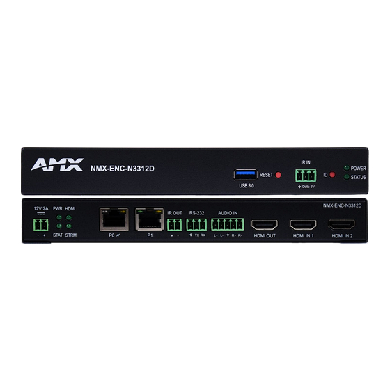
Introducing Your New N3300 Series Devices Introducing Your New N3300D Series Devices Product Overview AMX SVSI N3300 Series Encoders and Decoders deliver the highest quality 4K60 H.26x and Dante AV- H video content at the lowest bandwidth to extend the reach of SVSI 4K60 networked AV solutions to the WAN for streaming, video to desktop, digital signage, set-top boxes, or mobile device applications. - Page 9 Introducing Your New N3300 Series Devices FIG. 1 N3312D Encoder Front Panel 1) 12VDC Input (not needed with PoE+) RS232 Connection 2) Status Indicators Analog Audio Input 3) RJ45 Auto-Sensing Gigabit Ethernet Switch Port — PoE+ Passthrough HDMI Video Out 4) RJ45 Auto-Sensing Gigabit Ethernet Switch Port HDMI 1 Video Input 5) IR Emitter Output Connection...
- Page 10 Introducing Your New N3300 Series Devices Front and Rear Panel Descriptions Front Panel USB Standard-A Port-Decoder For Recording, Connect up to a 2TB USB drive RESET button Recessed pushbutton. Press to initiate a “warm restart” which causes the processor to reset, but not lose power.
-
Page 11: Installing And Configuring Your Av Equipment
Installing and Configuring Your AV Equipment Installing and Configuring Your AV Equipment This chapter provides an installation overview as well as a detailed step-by-step process for installation. If you encounter any problems, refer to the Troubleshooting section for help. Installation Overview The N3300D Encoders and Decoders have multiple configuration and installation options. -
Page 12: Mounting Options
Installing and Configuring Your AV Equipment Mounting Options The N3300D units are available in stand-alone and card versions. The stand-alone version can be free standing, surface mounted, wall mounted, or rack mounted. All cards must be rack mounted using the N9206 Card Cage (sold separately). Surface and Wall Mounting To mount your N3300D stand-alone unit to a flat surface or wall, follow these steps: Remove the four screws from the bottom of the unit and use them to attach the mounting wings (not included in shipment -... - Page 13 Installing and Configuring Your AV Equipment FIG. 7 Rack Mounting Cards Align the thumb screw on back plate before seating card into cage. Firmly seat the card and tighten the thumb screw by hand to secure card placement. Use one of the six Phoenix connector cables (included in shipment with the Encoder/Decoder Card) to connect the card’s 12VDC input Phoenix connector to one of the cage’s six 12VDC outputs.
-
Page 14: Step-By-Step Installation Instructions
Installing and Configuring Your AV Equipment Step-by-Step Installation Instructions This section provides step-by-step guidance for installing and configuring equipment from the N-Series product family on your network. The steps provided here assume the following to be true: There are switches operational on the network. N-Series equipment can operate on many different brands of networking equipment. - Page 15 Installing and Configuring Your AV Equipment Scroll down in the list to the Internet Protocol Version 4 option. Highlight it and click the Properties button. N3312D/N3322D Manual...
-
Page 16: Step 2: Connecting Decoders To The Network
Installing and Configuring Your AV Equipment address option and enter the static IP address provided to you by your network administrator. NOTE: If the computer does not need Internet access, you can simply enter a unique 169.254.xxx.xxx IP address with a 255.255.0.0 subnet mask. -
Page 17: Step 3: Connecting Encoders To The Network And Configuring Stream Settings
Installing and Configuring Your AV Equipment Once the Decoders and displays are connected and powered up, the LocalPlay screen appears on the displays. NOTE: If the LocalPlay screen does not appear, refer to the chapter Troubleshooting on page 100 for more guidance. NOTE: In order for the unit to receive PoE+, it must be connected to a switch or other equipment that has a PoE+ PSE (Power Sourcing Equipment) port. - Page 18 Installing and Configuring Your AV Equipment Encoders listed along the top Decoders listed along the bottom FIG. 11 Video Matrix Page Double-click the Encoder’s name in the list. The Login page is displayed (see Figure 12). If prompted, use the following default login credentials to log in for the first time.
-
Page 19: Step 4: Configuring Decoder And Encoder Ip Addresses (If Needed)
Installing and Configuring Your AV Equipment FIG. 13 Changing Stream Setting Repeat these steps until all Encoders are connected to the network and configured with an appropriate Stream number. NOTE: Each Encoder’s Stream number must be unique to all other Encoders on the network. NOTE: Screen-by-screen descriptions of the web interface options are provided for your reference in the Encoder Configuration Decoder Configuration... -
Page 20: Option 2: Assigning Ip Addresses To Multiple Units (Using Csv Files)
Installing and Configuring Your AV Equipment FIG. 14 IP Setup of the Network settings Click the Save button. Return to the Settings page through the newly configured IP address. Option 2: Assigning IP Addresses to Multiple Units (using CSV files) N-Able can export and import CSV files. -
Page 21: Step 5: Connecting Encoders To An Input Source
Installing and Configuring Your AV Equipment Step 5: Connecting Encoders to an Input Source Having already connected the Encoder(s) to the network and made the appropriate settings changes (as described in Step 3 4), you can now connect to the appropriate AV source(s). This connection from an Encoder HDMI IN port to an input source Step is accomplished using either an HDMI cable or DVI-I (through adapter). -
Page 22: Switching And Scaling Options
Installing and Configuring Your AV Equipment Switching and Scaling Options N-Series Encoders and Decoders make up a true AV matrix solution. In other words, one input can go to any or all outputs. Decoders have internal scaling capabilities. Keep the following in mind: The input of an Encoder is the video and/or audio signal going into the Encoder. -
Page 23: Control Options
Installing and Configuring Your AV Equipment Control Options For the most part, once the initial setup is complete, you will be primarily managing/configuring the Decoders. To better understand, think of Encoders as radio stations and Decoders as car radios. The Encoders are supplying the streams and, using the Decoders, you can “tune in”... -
Page 24: Encoder Configuration Options
Encoder Configuration Options Encoder Configuration Options This chapter defines N3312D Encoder configuration options. For ease of navigation, it is organized to reflect the graphical user interface (GUI). From any main page in the GUI, you can access all other main pages by clicking the links in the top navigation bar. Figure 17 shows the navigation bar and provides hot links to the sections of this chapter which describe each main page. -
Page 25: Home Page
Encoder Configuration Options Home Page Click the Home link at the top of any of the main web pages to access the page shown in Figure 18. This page is divided into several sections and has links to other dialog boxes for additional configuration options. Refer to the following sections for detailed descriptions: Stream Setup Settings Section on page 26... -
Page 26: Stream Setup Section
Encoder Configuration Options Stream Setup Section The Stream Setup section of the Home page is shown in Figure 19. Options are described in TABLE 1. FIG. 19 Device Settings Section TABLE 1 Home Page: Stream Settings Section Option Description Notes Device Name Enter a user-friendly name for the unit. -
Page 27: Management Setup Settings
Encoder Configuration Options Management Setup Settings The Management Setup section of the Home page is shown in Figure 20. Options are described in TABLE 2. FIG. 20 Management Setup Settings TABLE 2 Home Page: Management Setup Settings Option Description Notes Settings Lock Enable to lock the Encoder IP settings and stream number, preventing automated processes (from N-Able... -
Page 28: Current Source Section
Encoder Configuration Options Current Source Section The Current Source section of the Home page is shown in Figure 21. Options are described in TABLE 3. FIG. 21 Current Source Section TABLE 3 Home Page: Current Source Section Option Description Notes When enabled the current source will be shown in the below The preview image is updated approximately Preview Image... -
Page 29: General Setup Section
Encoder Configuration Options General Setup Section The General Setup section of the Home page is shown in Figure 22. Options are described in TABLE 4. FIG. 22 General Setup Section TABLE 4 Home Page: General Setup Section Option Description Notes Enable Send Status Enables the encoder to send a periodic status packet to the Send Status Address listed. -
Page 30: Network Page
Encoder Configuration Options Network Page Click the Network link at the top of any of the main web pages to access the page shown in Figure 23. This page is divided into several sections and has links to other dialog boxes for additional configuration options. Refer to the following sections for detailed descriptions: IP Setup Settings Section on page 31... -
Page 31: General Section - Ip Setup
Encoder Configuration Options General Section – IP Setup The General Section of the IP Setup on the Network page is shown in Figure 24. Options are described in Table 5. FIG. 24 General Section TABLE 5 Network Page: General Section of IP Setup Option Description Notes... -
Page 32: Ipv4 Section - Ip Setup
Encoder Configuration Options IPv4 Section – IP Setup The IPv4 section of the IP Setup on the Network page is shown in Figure 25. Options are described in Table 6. FIG. 25 IPv4 Section TABLE 6 Network Page: IPv4 Section of IP Setup Option Description Notes... -
Page 33: Ipv6 Section - Ip Setup
Encoder Configuration Options IPv6 Section – IP Setup The IPv6 section of the IP Setup on the Network page is shown in Figure 26. Options are described in Table 7. FIG. 26 IPv6 Section TABLE 7 Network Page: IPv6 Section of IP Setup Option Description Notes... -
Page 34: Date/Time
Encoder Configuration Options Date/Time The Date/Time section of the Network page is shown in Figure 27. Options are described in Table 8. FIG. 27 Date/Time Section TABLE 8 Network Page: Date/Time Option Description Notes Displays the current date and time of the unit. Current Date and Time Used to select the offset for the NTP time. - Page 35 Encoder Configuration Options 802.1x The 802.1x section of the Network page is shown in Figure 28. Options are described in Table 9. FIG. 28 802.1x Section TABLE 9 Network Page: 802.1x Option Description Notes When enabled will allow the device to be used with 802.1x IEEE 802.1x network configurations.
-
Page 36: Video/Audio Page
Encoder Configuration Options Video/Audio Page Click the Video/Audio link at the top of any of the main web pages to access the page shown in Figure 29. This page is divided into several sections and has links to other dialog boxes for additional configuration options. Refer to the following sections for detailed descriptions: Video Settings on page 37... -
Page 37: Stream Video Section - Svsi Stream - Video Section
Encoder Configuration Options Stream Video Section – SVSI Stream – Video Section The Stream Video section of the SVSI Stream section of the Video section on the Video/Audio page is shown in Figure 30. Options are described in Table 10. FIG. -
Page 38: Current Source Section - Svsi Stream - Video Section
Encoder Configuration Options Current Source Section – SVSI Stream – Video Section The Current Source section of the SVSI Stream section of the Video section on the Video/Audio page is shown in Figure 31. Options are described in Table 11. FIG. -
Page 39: Video Quality Section - Svsi Stream - Video Section
Encoder Configuration Options Video Quality Section – SVSI Stream – Video Section The Video Quality Section of the SVSI Stream section of the Video section on the Video/Audio page is shown in Figure 32. Options are described in Table 12. FIG. -
Page 40: Stream Video Section - H26X Stream - Video Section
Encoder Configuration Options Stream Video Section – H26x Stream – Video Section The Stream Video section of the H26x Stream section of the Video section on the Video/Audio page is shown in Figure 33. Options are described in Table 13. FIG. -
Page 41: General Section - Hdmi Pass-Thru - Video Section
Encoder Configuration Options General Section – HDMI Pass-thru - Video section The General section of the HDMI Pass-thru section of the Video section on the Video/Audio page is shown in Figure 34. Options are described in Table 14. FIG. 34 General Section TABLE 14 Video/Audio: General section of the HDMI Pass-thru section of the Video tab... -
Page 42: Current Source Section - Hdmi Pass-Thru - Video Section
Encoder Configuration Options Current Source Section – HDMI Pass-thru - Video section The Current Source section of the HDMI Pass-thru section of the Video section on the Video/Audio page is shown in Figure 35. Options are described in Table 15. FIG. -
Page 43: Status Section - Hdmi Pass-Thru - Video Section
Encoder Configuration Options Status Section – HDMI Pass-thru - Video section The Status section of the HDMI Pass-thru section of the Video section on the Video/Audio page is shown in Figure 35. Options are described in Table 15. FIG. 36 Status Section TABLE 16 Video/Audio: Status section of the HDMI Pass-thru section of the Video tab... -
Page 44: Audio Settings Section - Audio Setup
Encoder Configuration Options Audio Settings Section – Audio Setup The Audio Settings section of the Audio on the Video/Audio page is shown in Figure 37. Options are described in Table 17. FIG. 37 Audio Section TABLE 17 Network Page: Audio Section of Audio Setup Option Description Notes... -
Page 45: Edid Section - Edid Setup
Encoder Configuration Options EDID Section – EDID Setup The EDID section of the EDID on the Video/Audio page is shown in Figure 38. Options are described in Table 18. FIG. 38 EDID Section TABLE 18 Network Page: Audio Section of Audio Setup Option Description Notes... -
Page 46: Record Section - Record
Encoder Configuration Options Record Section – Record The Record section of the Record on the Video/Audio page is shown in Figure 39. Options are described in Table 19. FIG. 39 Record Section TABLE 19 Record Page: USB Record Port Option Description Notes Select to enable the USB recording function... - Page 47 Encoder Configuration Options TABLE 21 Record Page: File Transfer Setup Option Description Notes Method of transferring the recording SFTP | FTP | Share Transfer Method Port used to connect to transfer the recording Used for FTP or SFTP Server Port Directory of where to transfer the recording Used for Share Server Directory...
-
Page 48: Security Page
Encoder Configuration Options Security Page Click the Security link at the top of any of the main web pages to access the page shown in Figure 40. This page is divided into several sections and has links to other dialog boxes for additional configuration options. Refer to the following sections for detailed descriptions: General Settings Section on page 49... -
Page 49: Web Page Section - General Setup
Encoder Configuration Options Web Page Section – General Setup The Web Page section of the General on the Security page is shown in Figure 41. Options are described in Table 22. FIG. 41 Web Page Section TABLE 22 Security Page: Web Page Section of General Option Description Notes... -
Page 50: Security Certificates Section - General Setup
Encoder Configuration Options Security Certificates Section – General Setup The Security Certificates section of the General on the Security page is shown in Figure 42. Options are described in Table 23. FIG. 42 Security Certificates Section TABLE 23 Security Page: Security Certificates Section of General Option Description Notes... -
Page 51: User Security Details Section - Users Setup
Encoder Configuration Options User Security Details Section – Users Setup The Security Certificates section of the Users on the Security page is shown in Figure 43. Options are described in Table 24. FIG. 43 User Security Details Section TABLE 24 Security Page: User Security Details Section of Users Option Description... -
Page 52: Ldap Section - Ldap Setup
Encoder Configuration Options LDAP Section – LDAP Setup The LDAP section of the LDAP on the Security page is shown in Figure 44. Options are described in Table 25. FIG. 44 LDAP Section TABLE 25 Security Page: LDAP Section of LDAP Option Description Notes... -
Page 53: Control Page
Decoder Configuration Options Control Page Click the Control link at the top of any of the main web pages to access the page shown in Figure 45. This page is divided into several sections and has links to other dialog boxes for additional configuration options. Refer to the following sections for detailed descriptions: Serial Settings on page 54... -
Page 54: Serial Commands - Serial Setup
Decoder Configuration Options Serial Commands – Serial Setup The Serial Commands section of the Serial on the Control page is shown in Figure 46. Options are described in Table 26. FIG. 46 Serial Commands Section TABLE 26 Control Page: Serial Commands Section of Serial Option Description Notes... -
Page 55: Rs232 Settings - Serial Setup
Decoder Configuration Options RS232 Settings – Serial Setup The RS232 Settings section of the Serial on the Control page is shown in Figure 47. Options are described in Table 27. FIG. 47 RS232 Settings Section TABLE 27 Control Page: RS232 Settings Section of Serial Option Description Notes... -
Page 56: Ir Command - Ir Setup
Decoder Configuration Options IR Command – IR Setup The IR Command section of the IR on the Control page is shown in Figure 48. Options are described in Table 28. FIG. 48 IR Command Section TABLE 28 Control Page: IR Command Section of IR Option Description Notes... -
Page 57: System Page
Decoder Configuration Options System Page Click the System link at the top of any of the main web pages to access the page shown in Figure 49.This page is divided into several sections and has links to other dialog boxes for additional configuration options. Refer to the following sections for detailed descriptions: Logs Section on page 58... -
Page 58: Command Log - Log
Decoder Configuration Options Command Log – Log The Command Log section of the Log on the System page is shown in Figure 50. Options are described in Table 29. FIG. 50 Command Log Section TABLE 29 System Page: Command Log Section of Log Option Description Notes... -
Page 59: Debug Log - Log
Decoder Configuration Options Debug Log – Log The Debug Log section of the Log on the System page is shown in Figure 51. Options are described in Table 30. FIG. 51 Debug Log Section TABLE 30 System Page: Debug Log Section of Log Option Description Notes... -
Page 60: Link Layer Discovery Protocol (Lldp) - Status
Decoder Configuration Options Link Layer Discovery Protocol (LLDP) – Status The LLDP section of the Status on the System page is shown in Figure 52. Options are described in Table 31. FIG. 52 LLDP Section TABLE 31 System Page: LLDP Section of Status Option Description Notes... -
Page 61: Status - Status
Decoder Configuration Options Status – Status The Status section of the Status on the System page is shown in Figure 53. Options are described in Table 32. FIG. 53 Status Section TABLE 32 System Page: Status Section of Status Option Description Notes Displays the status of the HDMI 1 input as either Connected or... -
Page 62: Current Source - Status
Decoder Configuration Options Current Source – Status The Current Source section of the Status on the System page is shown in Figure 54. Options are described in Table 33. FIG. 54 Current Source Section TABLE 33 System Page: Current Source of Status Option Description Notes... -
Page 63: Software - Status
Decoder Configuration Options Software – Status The Software section of the Status on the System page is shown in Figure 55. Options are described in Table 34. FIG. 55 Current Source Section TABLE 34 System Page: Current Source of Status Option Description Notes... -
Page 64: Decoder Configuration Options
Decoder Configuration Options Decoder Configuration Options This chapter defines N3322D Decoder configuration options. For ease of navigation, it is organized to reflect the graphical user interface (GUI). As explained previously in the Encoder Configuration Options section on page 24, you can access the GUI main pages by clicking the links in the top navigation bar. -
Page 65: Home Page
Decoder Configuration Options Home Page Click the Home link at the top of any of the main web pages to access the page shown in Figure 56. This page is divided into several sections and has links to other dialog boxes for additional configuration options. Refer to the following sections for detailed descriptions: Stream Setup Settings Section on page 66... -
Page 66: Stream Setup Section
Decoder Configuration Options Stream Setup Section The Stream Setup section of the Home page is shown in Figure 57. Options are described in Table 35. FIG. 57 Device Settings Section TABLE 35 Home Page: Stream Settings Section Option Description Notes Device Name More descriptive names in this field help you organize Enter a user-friendly name for the unit. -
Page 67: Management Setup Settings
Decoder Configuration Options Management Setup Settings The Management Setup section of the Home page is shown in Figure 58. Options are described in Table 36. FIG. 58 Management Setup Settings TABLE 36 Home Page: Management Setup Settings Option Description Notes Settings Lock Enable to lock the Decoder IP settings and stream number, preventing automated processes (from N-Able... -
Page 68: Current Source Section
Decoder Configuration Options Current Source Section The Current Source section of the Home page is shown in Figure 59. Options are described in Table 37. FIG. 59 Current Source Section TABLE 37 Home Page: Current Source Section Option Description Notes When enabled the current source will be shown in the below The preview image is updated approximately Preview Image... -
Page 69: General Setup Section
Decoder Configuration Options General Setup Section The General Setup section of the Home page is shown in Figure 60. Options are described in Table 38. FIG. 60 General Setup Section TABLE 38 Home Page: General Setup Section Option Description Notes IGMP Join on stream When enabled will send IGMP Join messages when no incoming stream is detected. -
Page 70: Network Page
Decoder Configuration Options Network Page Click the Network link at the top of any of the main web pages to access the page shown in Figure 61. This page is divided into several sections and has links to other dialog boxes for additional configuration options. Refer to the following sections for detailed descriptions: IP Setup Settings Section on page 71... -
Page 71: General Section -Ip Setup
Decoder Configuration Options General Section –IP Setup The General Section of the IP Setup on the Network page is shown in Figure 62. Options are described in Table 39. FIG. 62 General Section TABLE 39 Network Page: General Section of IP Setup Option Description Notes... -
Page 72: Ipv4 Section -Ip Setup
Decoder Configuration Options IPv4 Section –IP Setup The IPv4 section of the IP Setup on the Network page is shown in Figure 63. Options are described in Table 40. FIG. 63 IPv4 Section TABLE 40 Network Page: IPv4 Section of IP Setup Option Description Notes... -
Page 73: Ipv6 Section -Ip Setup
Decoder Configuration Options IPv6 Section –IP Setup The IPv6 section of the IP Setup on the Network page is shown in Figure 64. Options are described in Table 41. FIG. 64 IPv6 Section TABLE 41 Network Page: IPv6 Section of IP Setup Option Description Notes... -
Page 74: Date/Time
Decoder Configuration Options Date/Time The Date/Time section of the Network page is shown in Figure 65. Options are described in Table 42. FIG. 65 Date/Time Section TABLE 42 Network Page: Date/Time Option Description Notes Displays the current date and time of the unit. Current Date and Time Time Zone... - Page 75 Decoder Configuration Options 802.1x The 802.1x section of the Network page is shown in Figure 66. Options are described in Table 43. FIG. 66 802.1x Section TABLE 43 Network Page: 802.1x Option Description Notes When enabled will allow the device to be used with 802.1x IEEE 802.1x network configurations.
-
Page 76: Video/Audio Page
Decoder Configuration Options Video/Audio Page Click the Video/Audio link at the top of any of the main web pages to access the page shown in Figure 67. This page is divided into several sections and has links to other dialog boxes for additional configuration options. Refer to the following sections for detailed descriptions: Video Settings on page 77... -
Page 77: Stream Video Section - Svsi/H.26X Stream Section - Video Section
Decoder Configuration Options Stream Video Section – SVSI/H.26x Stream Section – Video Section The Stream Video section of the SVSI/H.26x Stream section of the Video section on the Video/Audio page is shown in Figure 68 or 69. Options are described in Table 44. FIG. -
Page 78: Current Source Section - Svsi/H.26X Stream Section - Video Section
Decoder Configuration Options Current Source Section – SVSI/H.26x Stream Section – Video Section The Current Source section of the SVSI/H.26x Stream section of the Video section on the Video/Audio page is shown in Figure 70. Options are described in Table 45. FIG. -
Page 79: General Section - Hdmi Out Section - Video Section
Decoder Configuration Options General Section – HDMI Out Section – Video Section The General section of the HDMI Out section of the Video section on the Video/Audio page is shown in Figure 71. Options are described in Table 46. FIG. 71 General Section TABLE 46 Video/Audio: General section of the HDMI Out section of the Video tab... -
Page 80: Cec Settings Section - Hdmi Out Section - Video Section
Decoder Configuration Options CEC Settings Section – HDMI Out Section – Video Section The CEC Settings section of the HDMI Out section of the Video section on the Video/Audio page is shown in Figure 72. Options are described in Table 47. FIG. -
Page 81: Current Source Section - Hdmi Out - Video Section
Decoder Configuration Options Current Source Section – HDMI Out - Video section The Current Source section of the HDMI Out section of the Video section on the Video/Audio page is shown in Figure 73. Options are described in Table 48. FIG. -
Page 82: Audio Section - Audio Setup
Decoder Configuration Options Audio Section – Audio Setup The Audio section of the Audio on the Video/Audio page is shown in Figure 74. Options are described in Table 49. FIG. 74 Audio Section TABLE 49 Network Page: Audio Section of Audio Setup Option Description Notes... -
Page 83: Edid Section - Edid Setup
Decoder Configuration Options EDID Section – EDID Setup The EDID section of the EDID on the Video/Audio page is shown in Figure 75. Options are described in Table 50. FIG. 75 EDID Section TABLE 50 Video Page: EDID Section of EDID Setup Option Description Notes... -
Page 84: Security Page
Decoder Configuration Options Security Page Click the Security link at the top of any of the main web pages to access the page shown in Figure 76. This page is divided into several sections and has links to other dialog boxes for additional configuration options. Refer to the following sections for detailed descriptions: General Settings Section on page 85... -
Page 85: Web Page Section - General Setup
Decoder Configuration Options Web Page Section – General Setup The Web Page section of the General on the Security page is shown in Figure 77. Options are described in Table 51. FIG. 77 Web Page Section TABLE 51 Security Page: Web Page Section of General Option Description Notes... -
Page 86: Security Certificates Section - General Setup
Decoder Configuration Options Security Certificates Section – General Setup The Security Certificates section of the General on the Security page is shown in Figure 78. Options are described in Table 52. FIG. 78 Security Certificates Section TABLE 52 Security Page: Security Certificates Section of General Option Description Notes... -
Page 87: User Security Details Section - Users Setup
Decoder Configuration Options User Security Details Section – Users Setup The Security Certificates section of the Users on the Security page is shown in Figure 79. Options are described in Table 53. FIG. 79 User Security Details Section TABLE 53 Security Page: User Security Details Section of Users Option Description... -
Page 88: Ldap Section - Ldap Setup
Decoder Configuration Options LDAP Section – LDAP Setup The LDAP section of the LDAP on the Security page is shown in Figure 80. Options are described in Table 54. FIG. 80 LDAP Section TABLE 54 Security Page: LDAP Section of LDAP Option Description Notes... -
Page 89: Control Page
Decoder Configuration Options Control Page Click the Control link at the top of any of the main web pages to access the page shown in Figure 81. This page is divided into several sections and has links to other dialog boxes for additional configuration options. Refer to the following sections for detailed descriptions: Serial Section settings on page 90 ... -
Page 90: Serial Commands - Serial Setup
Decoder Configuration Options Serial Commands – Serial Setup The Serial Commands section of the Serial on the Control page is shown in Figure 82. Options are described in Table 55. FIG. 82 Serial Commands Section TABLE 55 Control Page: Serial Commands Section of Serial Option Description Notes... -
Page 91: Rs232 Settings - Serial Setup
Decoder Configuration Options RS232 Settings – Serial Setup The RS232 Settings section of the Serial on the Control page is shown in Figure 83. Options are described in Table 56. FIG. 83 RS232 Settings Section TABLE 56 Control Page: RS232 Settings Section of Serial Option Description Notes... -
Page 92: Ir Command - Ir Setup
Decoder Configuration Options IR Command – IR Setup The IR Command section of the IR on the Control page is shown in Figure 84. Options are described in Table 57. FIG. 84 IR Command Section TABLE 57 Control Page: IR Command Section of IR Option Description Notes... -
Page 93: System Page
Decoder Configuration Options System Page Click the System link at the top of any of the main web pages to access the page shown in Figure 85. This page is divided into several sections and has links to other dialog boxes for additional configuration options. Refer to the following sections for detailed descriptions: Logs Section on page 94 ... -
Page 94: Command Log - Log
Decoder Configuration Options Command Log – Log The Command Log section of the Log on the System page is shown in Figure 86. Options are described in Table 58. FIG. 86 Command Log Section TABLE 58 System Page: Command Log Section of Log Option Description Notes... -
Page 95: Debug Log - Log
Decoder Configuration Options Debug Log – Log The Debug Log section of the Log on the System page is shown in Figure 87. Options are described in Table 59. FIG. 87 Debug Log Section TABLE 59 System Page: Debug Log Section of Log Option Description Notes... -
Page 96: Link Layer Discovery Protocol (Lldp) - Status
Decoder Configuration Options Link Layer Discovery Protocol (LLDP) – Status The LLDP section of the Status on the System page is shown in Figure 88. Options are described in Table 60. FIG. 88 LLDP Section TABLE 60 System Page: LLDP Section of Status Option Description Notes... -
Page 97: Status - Status
Decoder Configuration Options Status – Status The Status section of the Status on the System page is shown in Figure 89. Options are described in Table 61. FIG. 89 Status Section TABLE 61 System Page: Status Section of Status Option Description Notes Status if the HDMI cable is connected. -
Page 98: Current Source - Status
Decoder Configuration Options Current Source – Status The Current Source section of the Status on the System page is shown in Figure 90. Options are described in Table 62. FIG. 90 Current Source Section TABLE 62 System Page: Current Source of Status Option Description Notes... -
Page 99: Software - Status
Decoder Configuration Options Software – Status The Software section of the Status on the System page is shown in Figure 91. Options are described in Table 63. FIG. 91 Current Source Section TABLE 63 System Page: Current Source of Status Option Description Notes... -
Page 100: Troubleshooting
Troubleshooting Troubleshooting This chapter contains possible solutions to some common issues. Should you encounter any problems not covered by these guidelines, please contact technical support. You can also visit our support webpage at suppot.harmanpro.com Issues Suggestions LocalPlay screen displays instead of the •... -
Page 101: Appendix A: Local/Host Play Error Screens
Troubleshooting Appendix A: Local/Host Play Error Screens This section shows and defines the status screens displayed by N3300D Series devices. FIG. 92 Host Play Screen Displayed when Decoder..and Encoder..Notes • is set to view an Encoder stream on •... - Page 102 Troubleshooting FIG. 94 Unsupported Input Resolution Screen Displayed when Decoder..and Encoder..Notes • is set to view a encoder • is being fed a video resolution This screen can be useful to show you that the stream on the network that is does not support Decoder is receiving the stream from the intended Encoder.
- Page 103 FIG. 96 Video Encrypted Screen Displayed when Decoder..Notes Make sure the decoder has the correct password for decrypting • is receiving a stream from an encoder it cannot decrypt the stream. To reset the password, go to the security page on both the encoder and decoder and click the reset button.
- Page 104 FIG. 98 HDCP Streaming Resolution Screen Displayed when Decoder..and Encoder..Notes • is set to view a encoder • setting of disabled HDCP This screen can be useful to show you that the stream on the network Advertisement Encoder is streaming HDCP material with the HDCP Advertisement disabled on the encoder.
-
Page 105: Appendix B: Minimum Network Requirements
Appendix B: Minimum Network Requirements The following list specifies the minimum network requirements that must be considered when deploying your N-Series equipment. These requirements cover the necessary protocols and features needed to drive N-Series streams. NOTE: Specific configuration recommendations are based off the Cisco Catalyst series, however this may vary. Managed Network Switch Gigabit Ethernet Internet Group Management Protocol (IGMP) Version 2... -
Page 106: Appendix C: Supported Resolutions
Appendix C: Supported Resolutions Resolution Refresh Rates YUV 4:4:4 YUV 4:2:2 YUV 4:2:0 Interlaced 4096x2160 (DCI) 4096x2160 4096x2160 4096x2160 4096x2160 4096x2160 4096x2160 3840x2160 (UHD) 3840x2160 3840x2160 3840x2160 3840x2160 3840x2160 3840x2160 3440x1440 (WQHD) 3440x1440 3440x1440 3440x1440 3440x1440 3440x1440 3440x1440 3840x1080 (DFHD) 3840x1080 3840x1080 3840x1080... - Page 107 Resolution Refresh Rates YUV 4:4:4 YUV 4:2:2 YUV 4:2:0 Interlaced 1366x768 1360x768 1280x1024 1280x960 1280x800 1280x768 1280x720 (HD) 1280x720 1280x720 1024x768 N3312D/N3322D Manual...
-
Page 108: Appendix D: Setup Guide For N3K/N2600S/N3510
Appendix D: Setup Guide for N3k/N2600S/N3510 The following list specifies the configuration required on the N3k, N2600S or N3510 to function with the N3300D series products. N3k Encoder to N3322D Decoder Mode Transport Stream Encoder Output Mode RTP Encapsulation Unicast Unicast Dest IP Unchecked SVSI Decoder... - Page 109 N3312D Encoder to N2622S Decoder H.26x Mode H.26x Profile Stream Output Mode H.26x Custom H.26x Custom H.26x Custom RTSP Note: N3312D Settings Set the N3312D ENC and N2622D DEC H26x IP Addresses in the same subnet. Set the N2622D DEC Receive Source to H.26x. Copy the stream URL from the N3312D ENC and paste it into the stream URL box on the N2622D DEC.
-
Page 110: Appendix E: Thumbnail And H.26X On Varia Panels
Appendix E: Thumbnail and H.26x on Varia Panels The following will outline the steps and some best practices to begin streaming H.26x to a Varia panel in VLC and provide a video preview to an object in G5. Thumbnail Preview: Open “Resource Manager”... - Page 111 Streaming Setup – (VLC App): Note: The section applies to configuring VLC to run as an app on the Varia Touch Panel. Configure the Encoder(s) for “Multi Stream” in the Encoder Mode setting in the Stream Setup section on the Home page.
- Page 112 Streaming Setup – (G5 App): Note: The section applies to configuring G5 to run video preview on Varia Touch Panel. Configure the Encoder(s) for “Multi Stream” in the Encoder Mode setting in the Stream Setup section on the Home page. Click save and wait for the confirmation message the settings have been applied.
- Page 113 © 2024 Harman. All rights reserved. SmartScale, NetLinx, Enova, AMX, AV FOR AN IT WORLD, and HARMAN, and their respective logos are registered trademarks of HARMAN. Oracle, Java and any other company or brand name referenced may be trademarks/registered trademarks of their respective companies.
Need help?
Do you have a question about the AMX N3300D Series and is the answer not in the manual?
Questions and answers