Table of Contents
Advertisement
Available languages
Available languages
Quick Links
Advertisement
Table of Contents

Related Manuals for Daewoo DAZJ Series


Summary of Contents for Daewoo DAZJ Series
- Page 1 DAZJ SERIES Drill Press/Taladro de banco USER'S MANUAL/MANUAL DE USUARIO www.daewoopowerproducts.com Manufactured under license of Daewoo International Corporation, Korea Fabricado bajo licencia de Daewoo International Corporation, Corea...
-
Page 2: Table Of Contents
INDEX 1. INTRODUCTION ............................. 2 2. IMPORTANT ............................2 3. GENERAL SAFETY RULES ........................2 4. CARE OF POWER TOOLS ........................2 5. ADDITIONAL SAFETY RULES FOR DRILL PRESSES ................ 3 6. PRODUCT OVERVIEW ........................... 5 7. SETTINGS AND AJUSTEMENTS ......................8 8. -
Page 3: Introduction
1. INTRODUCTION Thank you for purchasing this drill press. This machine has been designed for drilling large or small holes in metal, wood, plastic etc. Before attempting to use this product, please read this manual thoroughly and follow the instructions carefully. In doing so you will ensure the safety of yourself and that of others around you, and you can look forward to your purchase giving you long and satisfactory service. -
Page 4: Additional Safety Rules For Drill Presses
that keys, wrenches and tools are removed from the machine. 4. Don’t force the machine and use the correct tool. It will do the job better and safer, at the rate for which it was intended. 5. ALWAYS disconnect the machine from the power supply before carrying out any servicing or changing of accessories. - Page 5 10. ALWAYS stop the drill before removing workpieces, work supports or scarp from the table. 11. Keep drills sharp and clean for best and safest performance. Follow instructions for changing accessories. 12. Adjust the table or depth stop to avoid drilling into the table surface. 13.
-
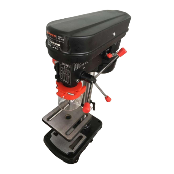
Page 6: Product Overview
6. PRODUCT OVERVIEW BENCH TYPE DRILL PRESS 1. Pulley Cover 2. Motor 3. Switch 4. Chuck guard 5. Chuck 6. Feed Handle 7. Table 8. Table Support 9. Belt Tension Lock knob 10. Column Support 11. Base 12. Main Housing 13. - Page 7 UNPACKING 1. The drill press is delivered with the components shown last page. Check the parts against the above list. Should there be any deficiencies or damage, you should contact your dealer immediately where the product was originally purchased. Do not discard the packaging until the machine is assembled.
- Page 8 5. Assemble table onto table support, tighten in place with table lock (Fig. 11). MAIN HOUSING 1. Lift the main housing and slide it down onto the column as far as it will go (Fig. 12). Before secu- ring the housing, ensure the spindle aligns with the table and base. 2.
-
Page 9: Settings And Ajustements
5. Once it is located a firm tap on the underside of the chuck with a soft hammer is required to secure it. The chuck & arbor are installed correctly if they cannot be pulley out with hand force (Fig. 21). - Page 10 2. After tilting the working table (Fig. 25) to appropriate position, re-tighten the bolt to secure its position. CAUTION: When the table is angled/tilted, ensure the workpiece is clamped to the table. INSTALLING STRAIGHT SHANK DRILL BITS 1. Using the chuck key, loosen the jaws of the chuck by rotating in an anti-clockwise direction (Fig. 26).
- Page 11 PRE-SETTING THE DRILLING DEPTH BENCH TYPE To set the depth of the hole, adjust the depth stop as follows: 1. Lower the chuck with the power OFF, until the drill bit touches the surface of the workpiece, and hold in that position. 2.
-
Page 12: Operation
2. Once the tension is released, the belt tension handle can be used to move the motor pulley closer to the idler pulley (Fig.38). 3. The belt is removed by lifting it over the lip of the pulley while rotating the pulley simultaneously (Fig.39). -
Page 13: Maintenance
DRILLING 1. Ensure the drill press is switched off and disconnected from the power supply. 2. Loosen the jaws of the chuck with the chuck key by turning in an anti-clockwise direction and insert the selected drill bit into the as far as it will go. 3. -
Page 14: Trouble Shooting
10. TROUBLE SHOOTING REMEDY PROBLEM PROBABLE CAUSE Noisy operation a. Incorrect belt tension. a. Adjust tension. (under load). b. Dry spindle. b. Remove spindle and quill c. Loose pulley. assembly and lubricate. d. Loose belt. c. Tighten pulley. e. Worn bearing. d. -
Page 15: Technical Specifications
11. TECHNICAL SPECIFICATIONS Model: DAZJ4113 Voltage/Frequency: 220-240 V ~ 50 Hz Power: 350 W Max drill capacity: 13 mm Spindle travel: 50 mm Column diameter: 46 mm Table size: 160x160 mm Base size: 300x185 mm Model: DAZJ4116 Voltage/Frequency: 220-240 V ~ 50 Hz Power: 550 W Drilling capacity: 16 mm Column diameter: 60 mm... -
Page 16: Introducción
1. INTRODUCCION Gracias por comprar este taladro. Esta máquina ha sido diseñada para taladrar agujeros grandes o pequeños en metal, madera, plástico, etc. Antes de intentar utilizar este producto, lea detenidamen- te este manual y siga cuidadosamente las instrucciones. Al hacerlo, se asegurará de su seguridad y la de los que le rodean, y puede esperar que su compra le brinde un servicio prolongado y satisfac- torio. -
Page 17: Reglas De Seguridad Adicionales En Taladros De Banco
3. Retire las llaves de ajuste antes de comenzar. Forme el hábito de verificar que las llaves y herra- mientas se hayan retirado de la máquina. 4. No fuerce la máquina y use la herramienta correcta. Hará el trabajo mejor y más seguro, a la velocidad para la que fue diseñado. - Page 18 material que se está perforando. 7. NUNCA deje el taladro desatendido mientras se está ejecutando. Apague la máquina y no se vaya hasta que se haya detenido por completo. 8. SIEMPRE elimine y almacene las brocas cuando haya terminado de trabajar. 9.
-
Page 19: Descripción Del Proudcto
6. DESCRIPCIÓN DEL PRODUCTO TIPO DE TALADRO DE BANCO 1. Cubierta de la polea 2. Motor 3. Interruptor 4. Guardia del mandril 5. Mandril 6. Mango de alimentación 7. Tabla 8. Soporte de tabla 9. Perilla de bloqueo de correa de tensión 10. - Page 20 DESEMPAQUE 1. La taladradora se entrega con los componentes que se muestran en la última página. Verifique las partes en la lista anterior. En caso de deficiencias o daños, debe ponerse en contacto con su distribuidor inmediatamente donde se compró originalmente el producto. No deseche el embalaje hasta que la máquina esté...
- Page 21 5. Monte la mesa sobre el soporte de la mesa, apriete en su lugar con el bloqueo de la mesa (Fig. 11). CARCASA PRINCIPAL 1. Levante la carcasa principal y deslícela hacia abajo sobre la columna tanto como sea posible (Fig.
-
Page 22: Configuraciones Y Ajustes
5. Una vez que esté ubicado, se requiere un golpe firme en la parte inferior del porta brocas con un martillo suave para asegurarlo. El plato y el eje están instalados correctamente si no pueden sacar- se con la fuerza de la mano (Fig. 21). 7. - Page 23 Después de inclinar la mesa de trabajo (Fig. 25) a la posición adecuada, vuelva a apretar el perno para asegurar su posición. PRECAUCIÓN: cuando la mesa está inclinada, asegúrese de que la pieza de trabajo esté sujeta a la mesa. INSTALACIÓN DE BROCAS DE TALADRADO RECTO 1.
- Page 24 firmemente en el eje. PREAJUSTE DEL TIPO DE BANCO DE PROFUNDIDAD DE PERFORACIÓN Para establecer la profundidad del orificio, ajuste el tope de profundidad de la siguiente manera: 1. Baje el porta brocas con la alimentación APAGADA, hasta que la broca toque la superficie de la pieza de trabajo y sosténgalo en esa posición.
-
Page 25: Operaciones
3. Consulte el cuadro dentro de la cubierta de la polea y coloque la correa en la polea de acuerdo con la velocidad del eje requerida. 4. Cuando la correa se haya colocado correctamente, vuelva a tensar alejando el motor del cabezal, hasta que la correa se desvíe aprox. -
Page 26: Mantenimiento
PERFORACIÓN 1. Asegúrese de que la taladradora esté apagada y desconectada de la fuente de alimentación. 2. Afloje las mordazas del porta brocas con la llave del porta brocas girándolas en sentido contrario a las agujas del reloj e inserte la broca seleccionada hasta el tope. 3. -
Page 27: Especificaciones Técnicas
DESPUÉS DE SU USO Retire todas las virutas de la máquina y limpie completamente todas las superficies. Los compo- nentes deben mantenerse secos, con las superficies mecanizadas ligeramente engrasadas. Siem- pre retire las brocas y guárdelas en un lugar seguro. 10. -
Page 28: Solución De Problemas
12. SOLUCIÓN DE PROBLEMAS REMEDIO PROBLEMA PROBABLE CAUSA a. Tensión incorrecta de la a. Ajusta la tensión. b. Retire el conjunto del correa. Operación husillo y el caño y lubrique. ruidosa (bajo b. Eje seco. c. Aprieta la polea. carga) c. - Page 29 Manufactured under license of Daewoo International Corporation, Korea...
Need help?
Do you have a question about the DAZJ Series and is the answer not in the manual?
Questions and answers