Table of Contents
Advertisement
Quick Links
ETC Installation Guide
Unison Echo
Overview
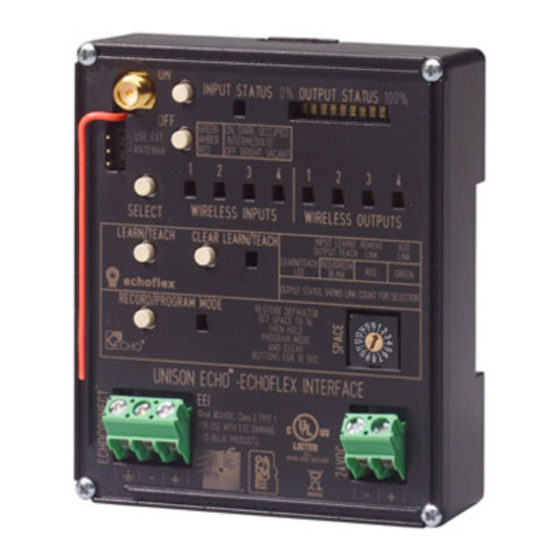
The Echo-Echoflex Interface (EEI) provides communication
between Unison Echo and Echoflex control systems by
converting wireless Echoflex controls into Unison Echo
actions, and enabling Unison Echo controls to control
wireless Echoflex power controllers.
The Echo-Echoflex Interface installs on standard DIN rail.
Accessory Kits
ETC provides a Low Voltage DIN rail Cover Kit (ETC part
number 7186A1218) that allows installation of the Echo-
Echoflex Interface to any standard 4" (10.16cm) junction box
(provided by others). Contact ETC for ordering details.
ETC offers an Echo-Echoflex Interface Antenna Kit (ETC part
number 7186K1001) that allows the installation of an external antenna. Contact ETC for ordering
information.
Specification
Note:
For use with ETC dimming and relay products. (902Mhz radio products only)
Ambient Environment
For indoor use only. Supports plenum rating.
• Operating temperature 0-50°C, 5-95% non-condensing humidity.
Electrical Specification
The EEI requires 24 Vdc (Class II) power, supplied by an external 24 Vdc power supply. Termination for this
connection is provided on a two position terminal, labeled 24 Vdc, accepting 26-14 AWG (0.4 - 1.6mm2)
wires (typically a 16AWG black and red wire pair).
Note:
Data and Wireless Signal
In addition to 24 Vdc, the Echo-Echoflex Interface requires EchoConnect
plus one ESD ground wire, supporting data and control to the Echo connect station bus. Reference
Electrical Specification
For communication with other wireless Echoflex devices, the Echo-Echoflex Interface includes a built-in 902
MHz radio. Communication is possible between the Echo-Echoflex Interface and other Echoflex wireless
devices that also support 902 MHz radio communication.
Corporate Headquarters
London, UK
Tel +44 (0)20 8896 1000
Rome, IT
Tel +39 (06) 32 111 683
Holzkirchen, DE
Hong Kong
Tel +852 2799 1220
Web:
www.etcconnect.com
7186M2103
Rev A
Echo-Echoflex Interface
®
-Echoflex Interface
Installation should follow all local codes and standard electrical practices.
NEC Class 2 product are to be wired in accordance with NEC Article 725 and local
jurisdiction requirements.
All power and control wiring should be installed and terminated by a qualified installer
and should follow standard wiring installation practices.
for more information about powering the Echo-Echoflex Interface.
Middleton, WI, USA
Tel +608 831 4116
Service: (UK)
Service: (UK)
service@etceurope.com
Tel +49 (80 24) 47 00-0
Service: (DE)
Service: (Asia)
service@etcasia.com
© 2016 ETC. All Rights Reserved.
Released 2016-03
ETC intends this document to be provided in its entirety.
Service: (Americas)
service@etceurope.com
techserv-hoki@etcconnect.com
Product information and specifications subject to change.
Page 1 of 14
™
, Belden 8471 (or equivalent)
service@etcconnect.com
Electronic Theatre Controls, Inc.
Advertisement
Table of Contents

Related Manuals for ETC Unison Echo-Echoflex


Summary of Contents for ETC Unison Echo-Echoflex
- Page 1 Echoflex Interface to any standard 4” (10.16cm) junction box (provided by others). Contact ETC for ordering details. ETC offers an Echo-Echoflex Interface Antenna Kit (ETC part number 7186K1001) that allows the installation of an external antenna. Contact ETC for ordering information. Specification Note: Installation should follow all local codes and standard electrical practices.
- Page 2 EEI to the Echoflex wireless stations and controllers. Additionally, ETC requires that the total combined length of an EchoConnect data run (using Belden 8471 or equivalent) must not exceed 1,640 feet (500m). This requirement should be considered when determining the location of the Echo-Echoflex Interface for installation.
- Page 3 ETC Installation Guide Echo-Echoflex Interface Installation Install Interface to DIN rail Step 1: Ensure the section of DIN rail to be used is mounted securely according to the manufacturers requirements. DIN rail is provided by others. Step 2: Hook the bottom of the EEI under the lower DIN rail as shown.
- Page 4 ETC Installation Guide Echo-Echoflex Interface Power Up and Operation Once the EEI is connected to the EchoConnect station bus and power is applied, the unit’s Wireless Input 1 LED will illuminate, indicating its ready for operation. Echoflex System Up to 25 compatible 902 MHz wireless Echoflex devices can be linked to the EEI through its inputs and outputs.
-
Page 5: User Interface
• When a Wireless Output is selected, pressing the [LEARN/TEACH] button “Teaches” the Wireless Output to Echoflex Controllers that are in “Learn” mode. Note: Reference the Echoflex Programming Guide, available as a download from the ETC website at www.etcconnect.com, for information about placing your Echoflex wireless devices in Learn or Teach mode. -
Page 6: Input Status
ETC Installation Guide Echo-Echoflex Interface LEDs Input Status The INPUT STATUS LED displays the state of the currently selected Wireless Input. When an Echoflex device is linked to the Echoflex Input and the Echoflex Input is selected, the LED reflects the current control status of the linked device. - Page 7 ETC Installation Guide Echo-Echoflex Interface System Note: The EEI supports a maximum of 25 Echoflex wireless devices. Wireless Inputs The four Wireless Inputs on the EEI convert Echoflex control inputs into Unison Echo Control system actions. Linking of Echoflex controls such as stations and sensors allows control of Echo presets.
- Page 8 ETC Installation Guide Echo-Echoflex Interface Double-tap Double-tap On and Off events perform the same action as the “Push” action for the linked Echoflex device type, except the event will execute in a 500ms time frame. • Double-tap On – Preset activation executed in a 500ms fade time.
- Page 9 ETC Installation Guide Echo-Echoflex Interface Note: Be careful with your testing. It is possible for manual controls to place the EEI out of state with maintained or state based wireless inputs. Double-tap Double-tap On and Off events perform the same action as the “Push” action for the linked Echoflex device type, except the event will execute in a 500ms time frame.
- Page 10 ETC Installation Guide Echo-Echoflex Interface Configuration Linking Echoflex Devices to Wireless Inputs and Outputs With a Wireless Input or Output selected, and the EEI in Learn/Teach Mode, the selected Wireless Input or Output LED lights and the OUTPUT STATUS LEDs indicate the number of Echoflex controls that are linked to the selected input or output.
-
Page 11: Program Mode
ETC Installation Guide Echo-Echoflex Interface Clearing the Linked Devices from Wireless Inputs and Outputs To clear all Echoflex devices from the selected Echoflex Input or Output on the EEI, press and hold the [CLEAR] button for five seconds. The LEARN/TEACH LED indicates in red, then goes out when the clear action is complete. - Page 12 ETC Installation Guide Echo-Echoflex Interface Step 2: Press the [SELECT] button until the Wireless Input to be configured is selected. The current preset number configured to the selection displays on the OUTPUT STATUS LED's. Step 3: Press the [ON] button to increase the preset number or press the [OFF] button to decrease the Preset number.
-
Page 13: Settings Configuration
ETC Installation Guide Echo-Echoflex Interface Settings Configuration Occupancy Sensor Input Settings Use the [SELECT] button to select the Echo input channel that has an occupancy sensor linked to it. Step 1: Press and hold the ON and OFF buttons for 5 seconds, until the Echo input status LED starts blinking RED. -
Page 14: Restore Defaults
ETC Installation Guide Echo-Echoflex Interface Step 3: Tap the ON button to cycle through different values. Input Output Status 1 Output Status Output Status Output Status Mode Status LED 2 LEDs 3 LEDs 4 LEDs Ingress 0sec (default) 30sec 1min...
Need help?
Do you have a question about the Unison Echo-Echoflex and is the answer not in the manual?
Questions and answers