Table of Contents
Advertisement
Quick Links
ETC Installation Guide
Contact and Demand Response Interfaces
Overview
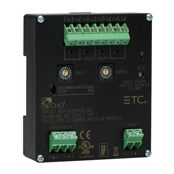
The Unison Echo
mounted devices that are available in the following configurations:
• Input Interface - accepts four momentary or maintained closures to
trigger control actions within an Echo control system.
• Demand Response Interface - accepts four maintained closures to
trigger demand response within an Echo control system.
• Output Interface - provides four normally open or normally closed
output relays controlled by actions in the Echo control system.
Contact Input Interface
Custom Configuration
This document guides you through the installation and basic local
configuration settings of the interface devices.
For more detailed information about custom configuration options available
using EchoAccess
system.
Note: To use the configuration settings applied using
Accessory Kit
ETC offers a Low Voltage DIN rail Cover Kit (ETC part number 7186A1218)
that allows installation of a Contact Interface to a 4" (10 cm) junction box
(provided by others). Contact ETC for ordering details.
®
Contact and Demand Response Interfaces are DIN rail
®
, reference the EchoAccess Mobile App integrated help
EchoAccess, the unit must be placed in Custom
configuration mode. Reference
Corporate Headquarters
Service (Americas)
service@etcconnect.com
London, UK
Tel +44 (0)20 8896 1000
Rome, IT
Tel +39 (06) 32 111 683
Holzkirchen, DE
Tel +49 (80 24) 47 00-0
Hong Kong
Tel +852 2799 1220
Web:
etcconnect.com
© 2018 Electronic Theatre Controls, Inc.
specifications subject to change.
7186M2144
Rev B
Released 2018-04
Middleton, Wisconsin, USA
Service: (UK)
Service: (UK)
Service: (DE)
Service: (Asia)
service@etcasia.com
ETC intends this document to be provided in its entirety.
Contact Output Interface
Set Configuration
Tel +608 831 4116
service@etceurope.com
service@etceurope.com
techserv-hoki@etcconnect.com
Product information and
Mode.
Advertisement
Table of Contents

Related Manuals for ETC Unison Echo


Summary of Contents for ETC Unison Echo
- Page 1 Set Configuration Mode. Accessory Kit ETC offers a Low Voltage DIN rail Cover Kit (ETC part number 7186A1218) that allows installation of a Contact Interface to a 4” (10 cm) junction box (provided by others). Contact ETC for ordering details.
- Page 2 Echo control system. EchoConnect is a bidirectional protocol that uses one pair of wires (data+ and data-). ETC recommends using Belden 8471 (or approved equal) Class 2 wire. The total combined length of an EchoConnect wire run (using Belden 8471, or equal) may not exceed 1,640 feet (500 m).
- Page 3 ETC Installation Guide Contact and Demand Response Interfaces Input and Demand Response Interface Wire Terminations The Input and Demand Response Interfaces provide four sets of terminals (“In” and “V out”) for connection to a momentary (Input Interface only) or maintained contact input. Terminals accept 24-12 AWG (0.2 mm -4 mm wire.
- Page 4 ETC Installation Guide Contact and Demand Response Interfaces Terminate Wiring Connect Auxiliary 24 VDC An external 24 VDC (Class 2) auxiliary power supply is required to power the interface. Terminate to the interface terminals labeled 24 VDC. Terminals accept 24-12 AWG (0.2-4 mm ) wires (typically a 16 AWG black and red wire pair).
- Page 5 • closing the closure twice (in rapid succession) performs a preset toggle with 1/2 second override timing Note: Particularly when considering machine driven applications, ETC recommends a minimum of 500 ms between any input changes to ensure transitions are reliably applied.
- Page 6 ETC Installation Guide Contact and Demand Response Interfaces Demand Response Interface: Activates Demand Response, affecting up four consecutive Echo Spaces, starting with the interface Space rotary switch setting. Example: Setting the Space switch to 3 results in control of Spaces 3, 4, 5, and 6.
- Page 7 ETC Installation Guide Contact and Demand Response Interfaces Demand Response Interface Inputs control Spaces determined by settings applied in the EchoAccess Mobile App. Note: Each Echo space can only have one assigned demand response input. Output Interface Relay outputs are controlled by the status of Presets 1-4 respectively.
- Page 8 ETC Installation Guide Contact and Demand Response Interfaces • For an Output Interface, set the Zone number (1 through 16 available) for the first output on the interface. The remaining outputs will be assigned consecutive zone numbers. The zone number does not apply while in Custom configuration mode.
Need help?
Do you have a question about the Unison Echo and is the answer not in the manual?
Questions and answers