Table of Contents
Advertisement
Quick Links
ETC Installation Guide
CueSystem Relay Interface
Overview
CueSystem Relay Interface connects to the CueSystem network to provide 120 V relay-driven outputs to
control external systems for cue indication, such as basket lights or LED tape light. Operating a CueSystem
Relay Interface requires a PC with the CueSystem PC application, a network switch, and a CueSystem desk.
Download the CueSystem PC application from
functionality.
Relay Interface with
C-Clamp Hanger
Instructional Safeguards
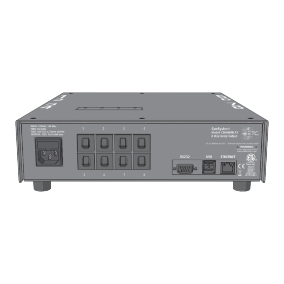
Input rating: 120 VAC, 50/60 Hz, 10 A Max
Output rating: 3 A Max per circuit, 120 VAC
Note:
CAUTION:
ATTENTION :
Corporate Headquarters
Global Offices
New York, NY | Orlando, FL | Los Angeles, CA | Austin, TX
Web
© 2021 Electronic Theatre Controls, Inc. | Trademark and patent info:
Product information and specifications subject to change. ETC intends this document to be provided in its entirety.
7493M2120 Rev A Released 2021-10
The CueSystem Relay Interface supports up to 10 A total connected load; more than three
output circuits cannot be loaded to 3 A at the same time. If you overload the outputs, the
Input Fuse will blow. To replace a blown fuse, see
RISK OF ELECTRIC SHOCK! Disconnect power before servicing.
RISQUE DE CHOC ÉLECTRIQUE! Couper l'alimentation avant l'entretien.
Middleton, WI, USA | +1 608 831 4116
London, UK | Rome, IT | Holzkirchen, DE | Paris, FR | Hong Kong | Dubai, UAE | Singapore
etcconnect.com
| Support
support.etcconnect.com
etcconnect.com/cuesystem
Relay Interface with
Pole-Mount Plate
Desktop Relay Interface
| Contact
etcconnect.com/contactETC
etcconnect.com/ip
for setup and advanced
Relay Interface with
Wall-Mount Plate
Input Fuse
on
page
4.
Advertisement
Table of Contents

Subscribe to Our Youtube Channel
Related Manuals for ETC CueSystem


Summary of Contents for ETC CueSystem
- Page 1 CueSystem Relay Interface connects to the CueSystem network to provide 120 V relay-driven outputs to control external systems for cue indication, such as basket lights or LED tape light. Operating a CueSystem Relay Interface requires a PC with the CueSystem PC application, a network switch, and a CueSystem desk.
- Page 2 Mount the Relay Interface The CueSystem Relay Interface includes mounting hardware for four mounting options: 1. wall-mount: flat plate with slotted holes 2. pole-mount: flat mounting plate with round holes, two U-bolts, four washers, and four 3/8 inch nuts 3.
- Page 3 ETC Installation Guide CueSystem Relay Interface Pole-Mount 1. Using the Phillips screwdriver and the four M4x8 mm screws, secure the pole-mount plate to the back of the enclosure. • The pole-mount plate has round holes. 2. Place one U-bolt around the pole.
- Page 4 Relay Operation Use the CueSystem PC application with a CueSystem desk to enable and disable the relays. There are eight relay LEDs on the front of the enclosure, one for each circuit (see G in the illustration above). An illuminated green LED means the relay is on.
- Page 5 Help from Technical Services If you experience difficulty during setup or installation of CueSystem, additional information is available from etcconnect.com, or by contacting ETC Technical Services at your local office listed at the bottom of the first page. Compliance For current and complete compliance information, view the product datasheets at etconnect.com/...
Need help?
Do you have a question about the CueSystem and is the answer not in the manual?
Questions and answers