Advertisement
Quick Links
Table of Contents
Table of Contents Limitation of Liability
Products Limited Warranty
Limited Warranty Limits and Exclusions
CHAPTER 1 GETTING STARTED
CHAPTER 2 INSTALLATION AND WIRING
DIAGRAM
General Wiring Diagram
Power Wiring Diagram
VOIP Diagram
Door Strike Wiring Diagram
Input Devices and Door Sensor Wiring Diagram
Satellite System Wiring Diagram
CHAPTER 3 KEYPAD CORRELATION
TABLE
CHAPTER 4 PROGRAMMING
Log-in to Programming Mode
Function Code 00: Change Master Code
Function Code 01: Add New Tenant Directory
file:///C|/PACH%20&%20COMPANY/PACH-CO.COM/PACH-CO.COM%202011-1/online_manual/qc1-qc1ip-qc2-qc2ip_manual-2.htm[1/17/2012 3:21:55 PM]
TABLE OF CONTENTS
Function Code 15: Initializing Event Recording
Function Code 16: Auto Unlock Schedule (AUS)
Function Code 17: Time Zone (TMZ)
Function Code 18: Holiday Zone (HLD)
Function Code 19: Directory Digit
Function Code 20: AUXIN1
Function Code 21: AUXIN2
Function Code 22: Do Not Disturb
Function Code 23: Lock-out Count
Function Code 24: Alarm
Function Code 25: Keypad Beep
Function Code26: Door Beep
Function Code 27: Talk Time
Function Code 28: Unlock Relay 1 Time
Function Code 29: Unlock Relay 2 Time
Function Code 33: Temporary Code
Function Code 34: Special Code
Function Code 35: Temporary Card
Function Code 36: Special Card
Function Code 38: System Acknowledge
Function Code 39: Disable and Enable Remote Access
Function Code 40: DTMF Relay 1
Function Code 41: DTMF Relay 2
Function Code 42: Relay 2 Mode
Function Code 43: Do Not Disturb Zone
Function Code 44: Disable Time Zone Relay
Function Code 45: Relay 1 and 2 Unlock Timer
Function Code 46: Firmware Version
Function Code 48: PBX Enable
Function Code 49: Edit Existing Access Code, Temporary Code and
Advertisement

Related Manuals for PACH & COMPANY QUANTUM QC1


Summary of Contents for PACH & COMPANY QUANTUM QC1
- Page 1 Table of Contents TABLE OF CONTENTS Table of Contents Limitation of Liability Function Code 15: Initializing Event Recording Function Code 16: Auto Unlock Schedule (AUS) Products Limited Warranty Function Code 17: Time Zone (TMZ) Function Code 18: Holiday Zone (HLD) Limited Warranty Limits and Exclusions Function Code 19: Directory Digit Function Code 20: AUXIN1...
-
Page 2: Limitations Of Liability
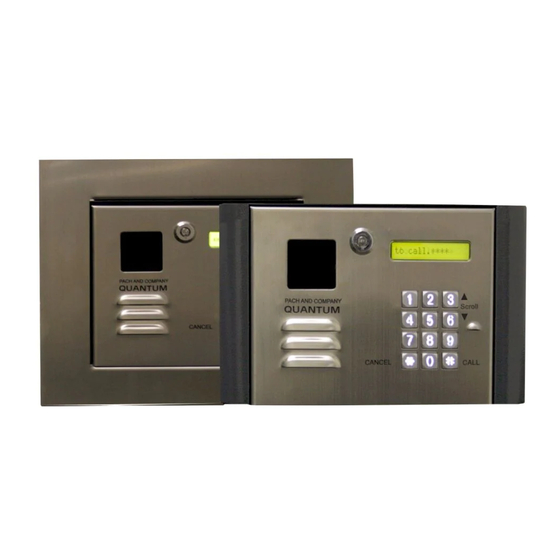
Table of Contents Special Code Function Code 02: Edit Existing Directory Function 50: Erase Memory to Factory Default Function Code 03: Delete Tenant Directory Function Code 51: Welcome Screen Function Code 04: Clear All Tenant Directories Function Code 05: Enable or disable Call CHAPTER 5 OPERATIONS Function Code 06: Add New Access Code Function Code 07: Delete Access Code... - Page 3 Pach & Company thanks and congratulates you on the purchase of your Quantum QC1-QC1IP-QC2-QC2IP Telephone Entry Access Control Systems. The manual is designed to guide you through the proper programming and use of the Quantum QC1-QC1IP-QC2-QC2IP. It is important for you to read and follow the manual completely.
- Page 4 Accessories and Replacement parts Visit our web site www.pach-co.com Unpacking the System All the items below come with the Quantum QC1-QC1IP-QC2-QC2IP. Contact Pach and Company for missing part(s) at (888) 678-7224, Monday-Friday 7:30 AM -3:30 PM Pacific Standard Time. file:///C|/PACH%20&%20COMPANY/PACH-CO.COM/PACH-CO.COM%202011-1/online_manual/qc1-qc1ip-qc2-qc2ip_manual-2.htm[1/17/2012 3:21:55 PM]...
- Page 5 Table of Contents CHAPTER 2 Installation and Wiring Diagram Follow the wiring diagram carefully. Improper installation will void the warranty. Please call technical support in case you have any difficulties during the installation. Click the selection below for different applications General Wiring Diagram Power Wiring Diagram VOIP Diagram...
- Page 6 Table of Contents Figure 2.1 General Wiring Diagram 2.2 Power Wiring Diagram file:///C|/PACH%20&%20COMPANY/PACH-CO.COM/PACH-CO.COM%202011-1/online_manual/qc1-qc1ip-qc2-qc2ip_manual-2.htm[1/17/2012 3:21:55 PM]...
- Page 7 Table of Contents Figure 2.2 Power Wiring Diagram 2.3 VOIP Wiring Diagram Compatibility issue may occur between the Quantum QC1-QC1IP-QC2-QC2IP and your VOIP line. file:///C|/PACH%20&%20COMPANY/PACH-CO.COM/PACH-CO.COM%202011-1/online_manual/qc1-qc1ip-qc2-qc2ip_manual-2.htm[1/17/2012 3:21:55 PM]...
- Page 8 Table of Contents Figure 2.3 VOIP Wiring Diagram 2.4 Door Strike Wiring Diagram file:///C|/PACH%20&%20COMPANY/PACH-CO.COM/PACH-CO.COM%202011-1/online_manual/qc1-qc1ip-qc2-qc2ip_manual-2.htm[1/17/2012 3:21:55 PM]...
- Page 9 Table of Contents Figure 2.4 Door Strike Wiring Diagram 2.5 Input Device and Door Sensor Wiring Diagram file:///C|/PACH%20&%20COMPANY/PACH-CO.COM/PACH-CO.COM%202011-1/online_manual/qc1-qc1ip-qc2-qc2ip_manual-2.htm[1/17/2012 3:21:55 PM]...
- Page 10 Table of Contents Figure 2.5 Input Device and Door Sensor Wiring Diagram 2.6 Satellite System Wiring Diagram Figure 2.6 Satellite System Wiring Diagram Assuming all wiring has been done properly according to chapter 2 then turn the system s power on as shown on figure number 10.
- Page 11 Table of Contents The QR5 buttons are lighted. Below are the correlation table for each key. = 1 _ . , ? : ; ! @ + - * / = # < > A B C a b c 2 D E F d e f 3 G H I g h i 4 J K L j k l 5...
- Page 12 Table of Contents Enter 01 then # Enter directory number 0-9 (directory is in single digit and cannot be changed) then # Chapter 3 for keypad layout Enter name up to 16 characters (name can be a person real name, apartment number, etc., directory will be sorted in alphabetical order) then press # Enter the tenant phone number up to 16-digit...
- Page 13 Table of Contents Chapter 3 for keypad layout Enter the a new tenant phone number up to 16-digit then press # or press without entering anything to keep the existing number. Return to step 3 to edit another tenant directory Function Code 03 - Delete Tenant Directory Log-in to programming Enter 03 then #...
- Page 14 Table of Contents Function Code 05 - Call Forwarding Enable or disable call. Default setting= 1 (enable). If 1 (disable) is selected, the system can't make calls Log-in to programming 2. Enter 30 then # 3. Enter 0= disable (default) pr 1= enable then press # Function Code 06 - Add New Access Code An access code is a keyless entry code to unlock the door.
- Page 15 Table of Contents Enter time zone 1-3 then press # Enter 00 hours) - 20 see function code 17 then press # Enter satellite system ID 0-7 (enter 0 if no satellite connected to the QR5) then press # Enter 0= no more additional time zone then press # and return to step 3 to program another access code...
- Page 16 3. Enter 4, 5, 6, 7 or 8 (default setting is 4 digit) then press # Function Code 10 - Add New Card or Transmitter A maximum of 100 cards or transmitters can be programmed into the Quantum QC1-QC1IP-QC2-QC2IP. Log-in to programming...
- Page 17 Table of Contents Enter door 1 or 2, or 3 for both then press # Enter time zone 1-3 then press # Enter 00 hours) - 20 see function code 17 then press # Enter satellite system ID 0-7 (enter 0 if no satellite connected to the QR5) then press # Enter 0= no more additional time zone then press # and return to...
- Page 18 Table of Contents Repeat this step to delete another code Function Code 12 - Clear All Cards or Transmitters Log-in to programming Enter 12 then # Enter 1 to clear all cards or transmitters then press # * to cancel Function Code 13 - Set Time Log-in to programming Enter 13 then #...
- Page 19 Table of Contents Enter YYYY/MM/DD YYYY= year MM= Month DD= Date then press # Enter 0= Sunday, 1= Monday, 2= Tuesday, 3= Wednesday, 4= Thursday, 5= Friday, 6= Saturday then press # 5. Enter 0= NO Daylight Saving Zone (Hawaii, Indiana and Arizona) 1=Daylight Saving Zone then press # Function Code 15 - Initializing Event recording The events are stored in the RAM buffer.
- Page 20 Table of Contents Enter AUS (0-9) then press # Enter 0= Delete the existing AUS the press # 1= Add AUS then press # Enter open time in military then press # Enter close time in military then press # Enter 0= Sunday, 1= Monday, 2= Tuesday, 3= Wednesday, 4= Thursday, 5= Friday, 6= Saturday then press #...
- Page 21 Table of Contents Log-in to programming Enter 17 then # Enter 01-20 (00=24 hours access automatically) then press # Enter 0= Delete the existing time zone then press # 1= add new time zone then press # Enter start time in military then press # Enter end time in military then press # Enter 0= Sunday, 1= Monday, 2= Tuesday, 3= Wednesday, 4= Thursday, 5= Friday, 6= Saturday...
- Page 22 Table of Contents Enter 18 then # Enter 01-20 then press # Enter 0= Delete the existing holiday zone then press # 1= add new holiday zone then press # 5. Enter month and date (i.e. 0704 for U.S.A Independence Day) then press # Return to step 3 to add more holiday zones.
- Page 23 Table of Contents 3. Enter 0= disable (default setting) 1= Enable control by relay 1 open door interval, see function code 28 2= relay 1 control by AUXIN1 then press # Function Code 21 - AUXIN2 AUXIN2 is used for input device such as postal lock, infrared sensor, exit button, etc.. AUXIN2 is associated with relay 2 Log-in to programming Enter 21 then # 3.
- Page 24 Table of Contents 2. Enter 23 then # 3. Enter 1-9 (default=3) then press # Function Code 24 Alarm The system will make have warning alarm if invalid code or card has been enter according to the setting on function code Log-in to programming 2.
- Page 25 Table of Contents 3. Enter 0= off, 1= On (default) then press # Function Code 27 Talk Time The amount of time the visitor can talk to the tenant. The timer starts as soon as the system is offhook. Log-in to programming 2.
- Page 26 Table of Contents Function Code 33 Temporary Code The code will be expired after being used a certain amount of times specified (1-10 times) in the programming, Up to 10 temporary codes can be programmed. Log-in to programming 2. Enter 33 then # 3.
- Page 27 Table of Contents 10. Enter Sat id 0-7 then press # (enter 0 if no satellite connected to the QR5) Enter 0= no more additional time zone then press # and return to step 3 to program another temporary code 1= add additional time zone then press # and return to step 8 * = exit programming...
- Page 28 Table of Contents 7. Enter 1= relay 1(door 1), 2= relay 2 (door 2) or 3= both relay then press # 8. Enter time zone 1-3 then press # 9. Enter 00 hours) - 20 see function code 17 then press # 10.
- Page 29 Table of Contents 5. Present the card or fob in front of the black window, the system will register the card or fob 8-digit number printed then press # Chapter 3 for keypad layout 6. Enter name and press # 7.
- Page 30 Table of Contents Log-in to programming Enter 36 then # 3. Enter 0= delete 1= add then press # 4. Enter code 01-10 then press # 5. Enter 4-8 digit code, see digit setting on function code 09 Chapter 3 for keypad layout 6.
- Page 31 Table of Contents 1= add additional time zone then press # and return to step 8 * = exit programming Function Code 38 System Acknowledge The system will answer incoming outside call after the number of rings set. If the line associated with the system is connected to fax machine, alarm panel or any answering device.
- Page 32 Table of Contents Log-in to programming 2. Enter 40 then # 3. Press 1-9 (9 is default setting) then press # Function Code 41 DTMF Relay 2 By default the DTMF remote opening relay 2 (door 2) key number is set to 8 means pressing 8 will remotely trigger relay 2 (door 2).
- Page 33 Table of Contents Log-in to programming 2. Enter 43 then # 3. Enter 0-9 then press # 4. Enter 0= delete, 1= add then press # 5. Enter start time (military time) the press # 6. Enter end time then press # (military time, end time must be later than start time, if start time: 22:00 hour and end time: 06:00, two time zone must be created (22:00 hour - 24:00 hour, 00:01 hour 06:00 hour) 7.
- Page 34 Table of Contents 3. Enter 0-9 then pres # Enter 0= Delete the existing time zone then press # 1= add new time zone then press # Enter start time in military then press # Enter end time in military then press # Enter 0= Sunday, 1= Monday, 2= Tuesday, 3= Wednesday, 4= Thursday, 5= Friday, 6= Saturday then press #...
- Page 35 Table of Contents or relay 2 (door 2) then press #, then press # Function Code 46 Firmware Version To check the system's firmware version Log-in to programming 2. Enter 46 then # Function Code 48 PBX Enable If the system is installed behind a Private Branch Exchange (PBX) then 9 is necessary before dialing an outside line. If this function is enabled then the system can only be dialing an outside line, it cannot dial the extension.
- Page 36 Table of Contents Log-in to programming 2. Enter 49 then # 3. Editing an Access Code click here Editing a Temporary Code, click here Editing a Special code, then click here Function Code 50 Erase Memory to Factory Default Warning: This function code will erase the memory to factory default, no way to restore them unless the database has been saved in the computer.
- Page 37 Function Code 09 5.4 Opening Door Using Card, Temporary Card, and Special Card The Quantum QC1-QC1IP-QC2-QC2IP has built-in card reader. The door can be access using UFOB, UCLAM or UISO. Card Standard Operation is used to open the door and door will be closed automatically, see...
- Page 38 5.5 Opening Door Using Transmitter, Temporary Code Transmitter, and Special Code Transmitter The Quantum QC1-QC1IP-QC2-QC2IP has built-in Radio Frequency (RF) Receiver. The transmitter will work in 300 feet radius open air with the transmitter antenna fully extended. The distance may vary depending on the environment.
- Page 39 Table of Contents The system must be install in Intercom and Call Forwarding Mode Wiring Diagram Call Forwarding Mode wiring Diagram Function code 38 must be set at least for 1 ring Function code 39 must be set to 1 4.
Need help?
Do you have a question about the QUANTUM QC1 and is the answer not in the manual?
Questions and answers