Advertisement
This bulletin is provided for technical reference and service related updates. If you have any questions, comments or do not wish to receive these e-mails, please reply to this e-mail
or call the Service Technical Support Group 800 478-1244.
This documentation can be used as a guide when inspecting and diagnosing failure associated with the AC
voltage output on the DA7000 series generator.
Use of an accurate multi-meter is necessary when inspecting the generator.
Safety precautions should be followed at all times when servicing this
equipment. Consult operations manual for more safety information.
To access components to be inspected
remove control panel, (4) Phillip head screws.
TB1 (terminal board 1)
TB2 (terminal board 2)
CB (circuit breaker)
RE1 (diode rectifier) R (resistor)
Mounted behind panel
TI_DA7000_Voltage_Diagnostic
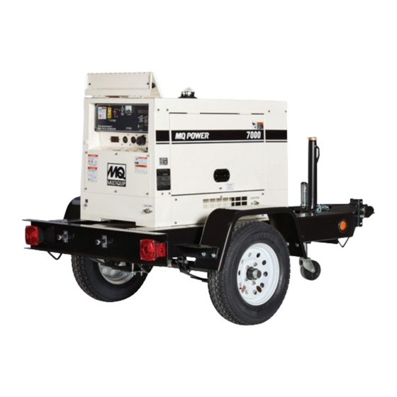
DA7000 Voltage Diagnostic
Component Identification and Location
Fuse Box
Product
Model: DA7000 Series
Screws
1
Group: Generator
05/19/2011
Advertisement
Table of Contents

Related Manuals for MULTIQUIP DA7000 Series


Summary of Contents for MULTIQUIP DA7000 Series
- Page 1 DA7000 Voltage Diagnostic This documentation can be used as a guide when inspecting and diagnosing failure associated with the AC voltage output on the DA7000 series generator. Use of an accurate multi-meter is necessary when inspecting the generator. Safety precautions should be followed at all times when servicing this equipment.
- Page 2 Technical Information Inspection Procedure Check the following with the engine off! • Inspect F4 fuse, (see page • Inspect (J) terminal on TB2 for 12V DC when starter switch key is in the run position, (see page Starter Switch ( MQ part# ) 3741059110 •...
- Page 3 Technical Information Excitation & Output Windings TB2 and Fuse Box F4 – 5amp ( MQ part# ) 0601806642 J & K Inspect fuse with multi-meter, ensure inside filament is intact. U & N N & V U & N provides 120V AC to the receptacles N &...
- Page 4 Technical Information Resistor & Rectifier RE1 & R & is mounted behind the panel by machined screws There are two rectifiers at this location, the top one is for excitation. (Diode Rectifier) ( MQ part# 0601823204 ) prevents voltage spikes or back feed in the circuit. (Resistor) ( MQ part# 0601842463 ) opposes the electrical current by producing a voltage drop...
- Page 5 Technical Information Engine Wire Diagram TI_DA7000_Voltage_Diagnostic 05/19/2011...
- Page 6 Technical Information Generator Wire Diagram TI_DA7000_Voltage_Diagnostic 05/19/2011...
Need help?
Do you have a question about the DA7000 Series and is the answer not in the manual?
Questions and answers